Linear actuator

A linear actuator, actuator unit technology, applied in piezoelectric devices/electrostrictive devices, piezoelectric effect/electrostrictive or magnetostrictive motors, generators/motors, etc., can solve the problem of inability to move , increased frictional resistance loss, large slider frictional resistance, etc.

Inactive Publication Date: 2005-07-13
SEIKO EPSON CORP
View PDF1 Cites 10 Cited by
  • Summary
  • Abstract
  • Description
  • Claims
  • Application Information

AI Technical Summary

Problems solved by technology

[0003] However, in this mechanism, since frictional driving is performed by relying on the thrust applied to the slider from the vibrating element, the frictional resistance between

Method used


Image

  • Linear actuator
  • Linear actuator
  • Linear actuator

Examples


Embodiment Construction

[0041] Hereinafter, preferred embodiments of the linear actuator of the present invention will be described with reference to the accompanying drawings.

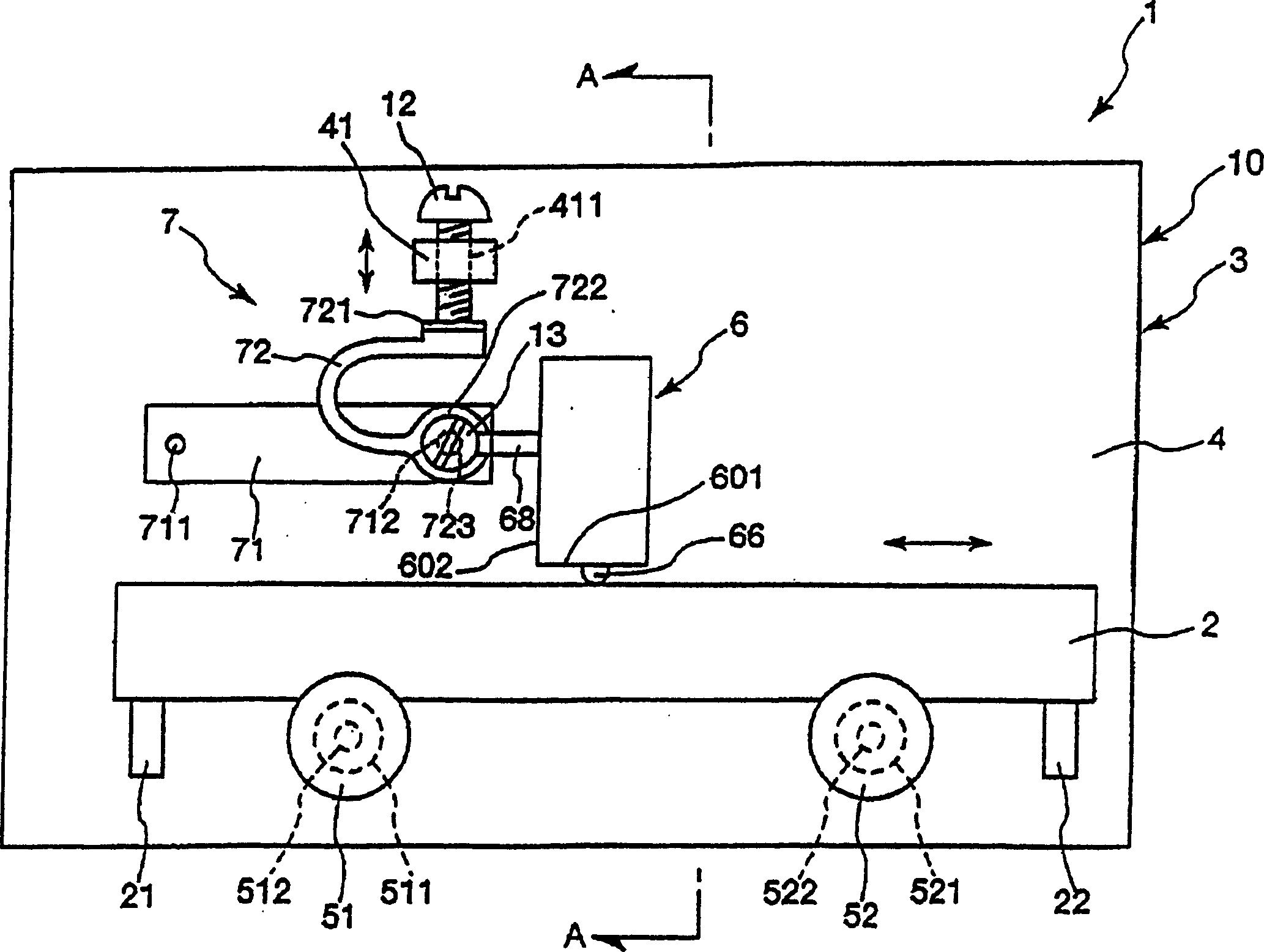
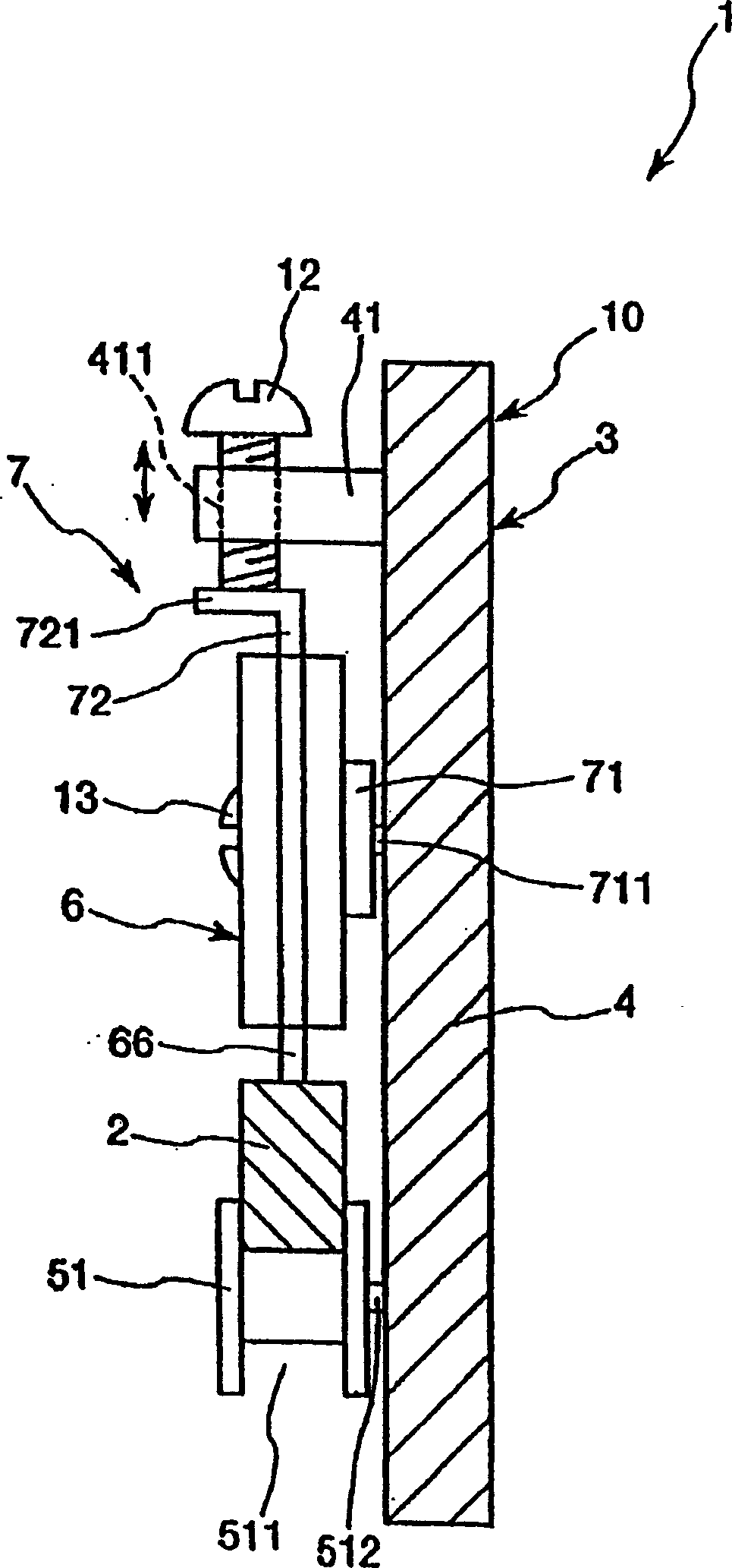
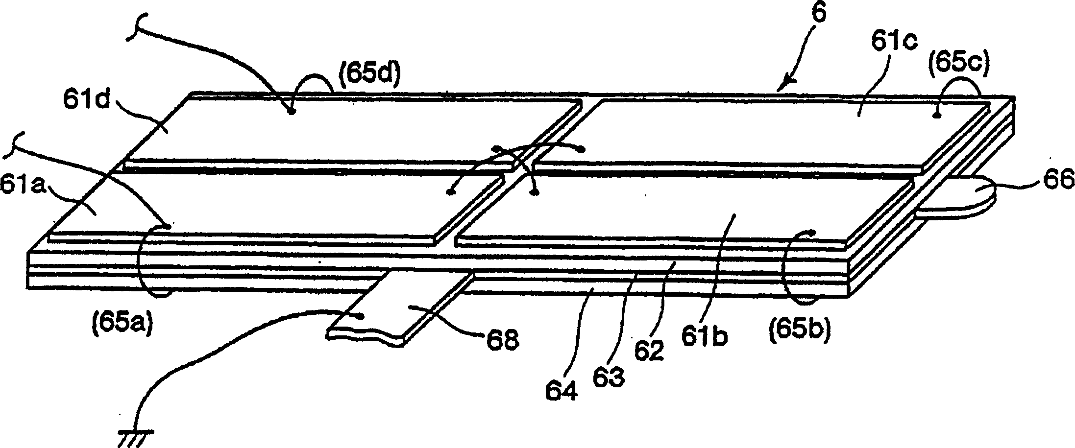
[0042] figure 1 is a plan view showing a first embodiment of the linear actuator according to the present invention. figure 2 yes figure 1 A cross-sectional view of the shown linear actuator taken along line A-A. image 3 yes figure 1 Perspective view of the vibrating element in the shown linear actuator. Figure 4 and Figure 5 are each shown figure 1 Plan view of the vibration state of the vibrating element in the shown linear actuator. Figure 6 is showing figure 1 A block diagram of the circuit configuration of the linear actuator is shown. Here, use the following figure 1 In the description of figure 1 The upper side is called "upper", the lower side is called "lower", the right side is called "right", and the left side is called "left".

[0043] The linear actuator 1 shown in these figures is an actuator th...


PUM


Abstract

A linear actuator is an actuator used to directly drive (move) a slide. The linear actuator has an actuator unit composed of: a slider; and an actuator main body on which the slider is movably provided for linear movement. The actuator body has: a base; a vibrating element for moving the slider; two rollers for movably supporting the slider; a pressing device for pressing the vibrating element into contact with the slider; and an energization circuit , for energizing each electrode of the vibrating element by selecting an energization mode of each electrode. Grooves are respectively formed on the outer peripheral surfaces of the rollers, and sliders are provided in the respective grooves.

Description

technical field [0001] The present invention relates to linear actuators. Background technique [0002] Japanese Patent Application Laid-Open No. Hei 7-184382 discloses a mechanism in which a slider movable relative to a shaft is provided and an AC voltage is applied to a piezoelectric element of a vibrating element (micromotor) so that The vibrating element vibrates so that this vibration applies a force to the slide, moving the slide along the axis. [0003] However, in this mechanism, since frictional driving is performed by relying on the thrust applied to the slider from the vibrating element, the frictional resistance between the slider and the shaft increases according to the thrust and a large loss occurs, and there are the following cases: The slider cannot move due to too much frictional resistance. Contents of the invention [0004] The object of the present invention is to provide a linear actuator which has a simple structure, has the advantages of miniaturi...

Claims


Application Information

Patent Timeline
IPC IPC(8): H01L41/09H02N2/02H02N2/06
CPCH02N2/004H02N2/0055H02N2/006H02N2/026H02N2/06
Inventor 宫泽修
Owner SEIKO EPSON CORP
Why Eureka
Try Eureka