
Bidirectional indraft type centrifugal fan and cooling apparatus for computer

A technology of centrifugal fan and cooling device, which is applied to components of pumping devices for elastic fluids, mechanical equipment, non-variable pumps, etc., and can solve problems such as difficult use of centrifugal fans

Inactive Publication Date: 2005-07-20
LG INNOTEK CO LTD
View PDF0 Cites 9 Cited by
  • Summary
  • Abstract
  • Description
  • Claims
  • Application Information

AI Technical Summary

Problems solved by technology

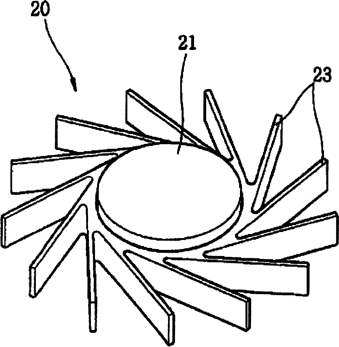
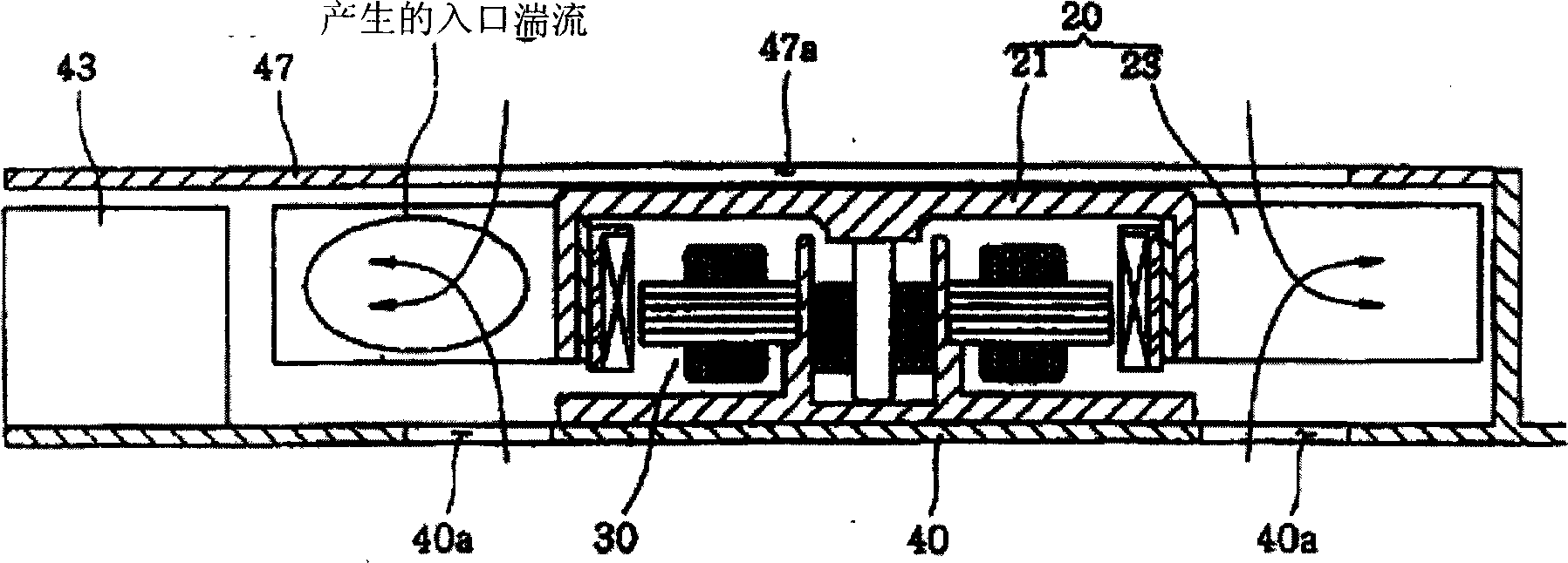
[0014] Also, although the centrifugal fan having the above structure can be used when it has a small number of blades, it is structurally difficult to use the centrifugal fan when it has many blades.

Method used


Image

  • Bidirectional indraft type centrifugal fan and cooling apparatus for computer
  • Bidirectional indraft type centrifugal fan and cooling apparatus for computer
  • Bidirectional indraft type centrifugal fan and cooling apparatus for computer

Examples


no. 1 example

[0035] Figure 3A is an exploded perspective view showing the centrifugal fan and cooling device according to the first embodiment of the present invention, which will be described below.

[0036] Such as Figure 3A As shown, centrifugal fan 100 includes a hub 110 , a disk 120 and a plurality of blades 130 . The hub 110 is made as a hollow cylinder with an opening at one end and a motor 240 therein ( Figure 3B ). The disc 120 is formed in the shape of a rim having an inner edge joined to an outer edge of the hub 110 . The blades 130 are arranged radially around the center of the hub 110 on the outer edge of the disc 120 at an angle to a line L extending from the radius of the disc 120 .

[0037] Describing this in detail, the blades 130 are arranged from the inside of the disk 120 towards the outside, and have one end or inner ends (inner ends) that are integrally arranged between the inner and outer edges of the disk 120, and the other One end or outward end protrudes f...

no. 2 example

[0056] Figure 7A is an exploded perspective view of a centrifugal fan according to a second embodiment of the present invention, and Figure 7B yes means Figure 7A Combined cross-sectional view of a centrifugal fan in application.

[0057] This embodiment will be described according to its difference compared with the first embodiment, wherein the number of blades 330 of the centrifugal fan 300 is at least 25 and is placed at the inlet 267 of the frame 260 and the cover 270 together with the disc 320 and between the inner and outer edges of 271. A multi-blade fan generally means a fan in which blades have an exit angle of about 90 degrees or more and the number of blades is 36 to 64. Since the double-suction multi-blade fan has a shorter blade chord length and functions as a rotating body to impart energy to the fluid, the outer ends of the blades 330 may be selectively covered by the frame 260 and the cover 270 .

[0058] Figure 7B It is shown that the disk 320 and th...


PUM


Abstract

A double suction centrifugal fan capable of bidirectionally sucking fluid and a cooling apparatus for a computer using the same. In the centrifugal fan and the cooling apparatus, a disk is provided between blades and a hub so that fluid is sucked to both faces of the disk and then discharged toward the blades. That is, interference between sucked fluid is minimized to restrain creation of turbulence flow, thereby reducing noise and improving efficiency. Also inner ends of the blades of the centrifugal fan are arranged in an inner portion of the disk to relatively shorten the chord length of the blades, resultantly reducing tonal noise owing to BPF and thermal deformation of the blades. Furthermore, since the magnitude of the disk is adjusted, the number of the blades in not restricted and the centrifugal fan of the invention and the cooling apparatus mounting the centrifugal fan therein can be applied to computers by restructuring the frame and the cover of the cooling apparatus.

Description

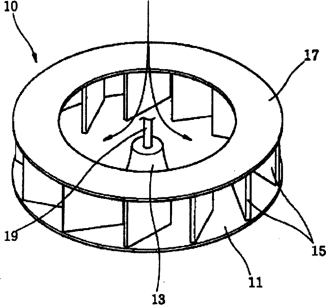
technical field [0001] The present invention relates to a cooling device for a computer, and in particular to a double-suction centrifugal fan capable of bidirectionally sucking fluid and a cooling device for a computer using the double-suction centrifugal fan. Background technique [0002] Traditional cooling devices generally use axial fans. However, laptops are more suitable to use centrifugal fans with higher static pressure than axial fans, because centrifugal fans have very high integration and large fluid air resistance. [0003] Centrifugal fans are generally classified into single-suction fans, which suck fluid in one direction, and double-suction fans, which suck fluid in two directions, according to the suction type. The traditional single-suction centrifugal fan will refer to figure 1 to describe. [0004] Such as figure 1 As shown, the centrifugal fan 10 has a circular support plate 11, a hub 13 on a central portion of the support plate 11, and a plurality o...

Claims


Application Information

Patent Timeline
IPC IPC(8): F04D29/28
CPCF04D29/281F04D29/28
Inventor 张盛旭
Owner LG INNOTEK CO LTD
Learn More