Check patentability & draft patents in minutes with Patsnap Eureka AI!

Method of producing fuses

A fuse and lead technology, used in fuse manufacturing, electrical components, electrical switches, etc., can solve problems such as defective fuses and difficult leads to be fixed in the required position.

Inactive Publication Date: 2005-07-20
PI
View PDF0 Cites 0 Cited by
  • Summary
  • Abstract
  • Description
  • Claims
  • Application Information

AI Technical Summary

Problems solved by technology

This makes it difficult to secure the leads in the desired position
Specifically, even after it has been assembled to the insulating base, the leads have a tendency to return to their original coiled form, resulting in defective fuses

Method used


Image

  • Method of producing fuses
  • Method of producing fuses
  • Method of producing fuses

Examples


Embodiment Construction

[0023] best practice

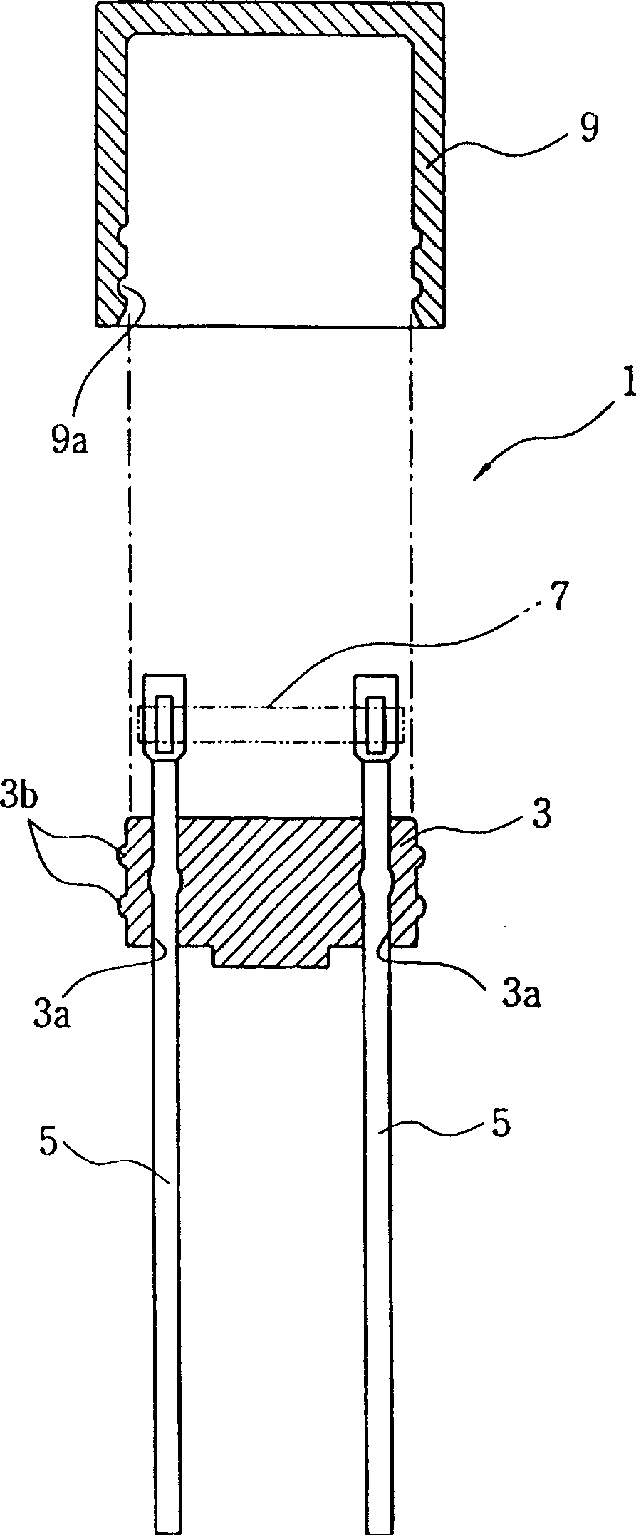
[0024] A preferred method of producing a fuse according to the present invention will be described below with reference to the accompanying drawings. In this document, the term "die-cut" refers to a semi-finished product obtained by stamping a metal sheet into a plurality of lead-conductor pairs.

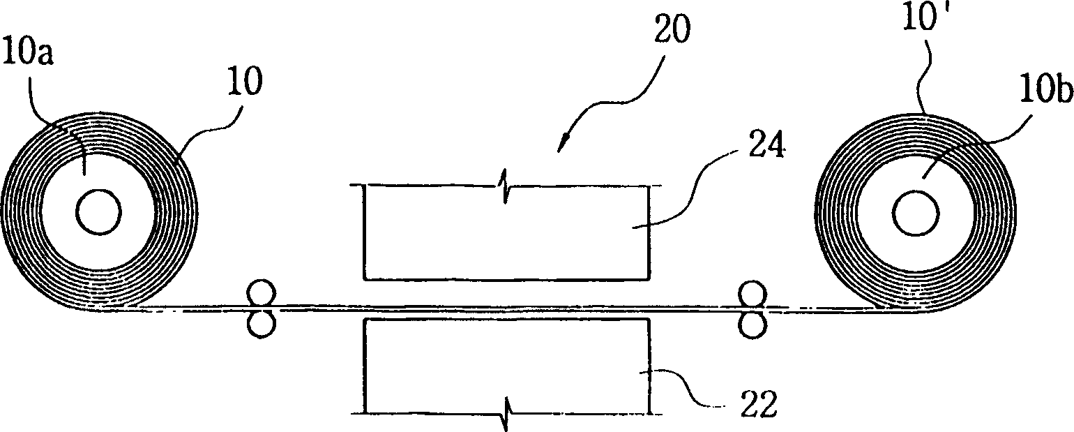
[0025] Figures 2A to 2H shows a series of steps employed in a method for producing a fuse according to a preferred embodiment of the present invention, and Figures 3A to 3E The configuration of the metal sheet formed in the various steps of the method of the invention is shown.

[0026] The fuse production method according to the present invention uses a metal sheet 10, such as Figure 2A As shown, it may be a coiled continuous strip. The sheet metal 10 is intermittently unwound from a supply reel 10a and conveyed to a take-up reel 10b. An example of the metal sheet 10 may be a copper sheet. The width and length of the metal piece 10 are appropriately ...


PUM


Abstract

A method is provided for producing fuses with an increased yield rate and in a highly automated fashion. The method comprises the steps of processing a metal sheet into a blank having a plurality of continuously distributed pairs of lead conductors, molding an insulator base integrally with each pair of the lead conductors, electrically interconnecting the lead conductors of the respective conductor pair with a fusible connector, and severing the lead conductors from the blank. Additionally, a protection cap is coupled to the insulator base in such a manner that the cap can enclose the fusible connector in its entirety.

Description

technical field [0001] The present invention relates to a method for producing fuses, and in particular to a method for producing high quality fuses with higher throughput and in a highly automated manner. Background technique [0002] As is well known to those of ordinary skill in the art, a fuse has a fusible metal connector that is melted by excessive current, thereby breaking. When a current higher than the specified value flows, the fusible metal connector breaks to automatically cut off the current, thereby protecting electronic parts and circuits. Such fuses have been developed in a variety of structures and forms. Recently, micro fuses have been developed that can be applied to small-sized electronic products. [0003] figure 1 A cross-sectional portion of an existing micro-fuse (hereinafter referred to simply as "fuse") is shown. Such as figure 1 As shown, the fuse 1 includes an insulating base 3 . The insulating base 3 is made of a disc-shaped member having a...

Claims


Application Information

Patent Timeline
Patent Type & Authority Applications(China)
IPC IPC(8): H01H85/04H01H11/00H01H69/02H01H85/041
CPCY10T29/49204Y10T29/49121Y10T29/49107Y10T29/49158H01H85/0417H01H69/02H01H11/0056H01H85/04
Inventor 金昌一
Owner PI
Features
  • R&D
  • Intellectual Property
  • Life Sciences
  • Materials
  • Tech Scout
  • Unparalleled Data Quality
  • Higher Quality Content
  • 60% Fewer Hallucinations
Learn More