

Lattice loading method for treating random distributed load on curved surface
A technology of distributing loads and spatial grids, applied in electrical digital data processing, special data processing applications, instruments, etc., can solve the problem of undistributed load processing, etc., and achieve the effect of easy operation, expansion of use range, and improvement of operation efficiency.
- Summary
- Abstract
- Description
- Claims
- Application Information
AI Technical Summary
Problems solved by technology
Method used
Image

Examples
Embodiment 1
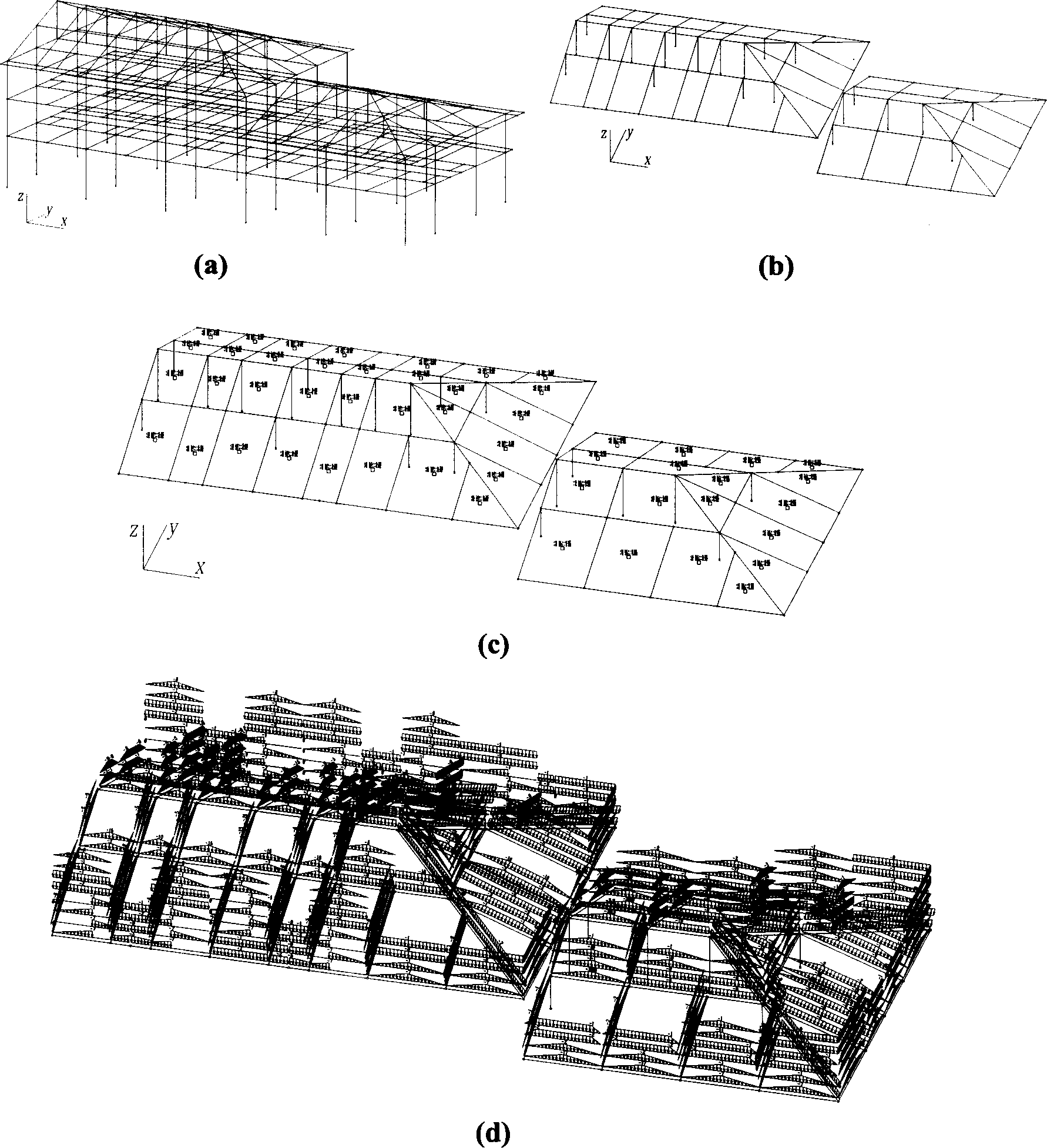
[0050] Such as figure 1 The complex sloping roof project shown in (a) has 3-story and 4-story sloping roofs, which are not connected to each other. The sloping roof is a cast-in-place concrete slab. The self-weight of the slab, the self-weight of other roof materials, the load of people on the roof, and the snow load are used as surface loads, which need to be derived to the roof beams.
[0051] Close the beams and columns of each layer below the slope roof, keep only the beams and columns of the slope roof, and perform 3D view conversion, so that the slope roof is unfolded on the view projection plane, as shown in the attached figure 1 (b) shown. Use the software to select all the beams and columns of the sloping roof at one time. Columns are rejected as cantilevered edges connected at only one end.
[0052] Utilizing the method of the invention, according to the two-dimensional plane figure on the view projection plane, a three-dimensional load grid in space and correspon...
Embodiment 2
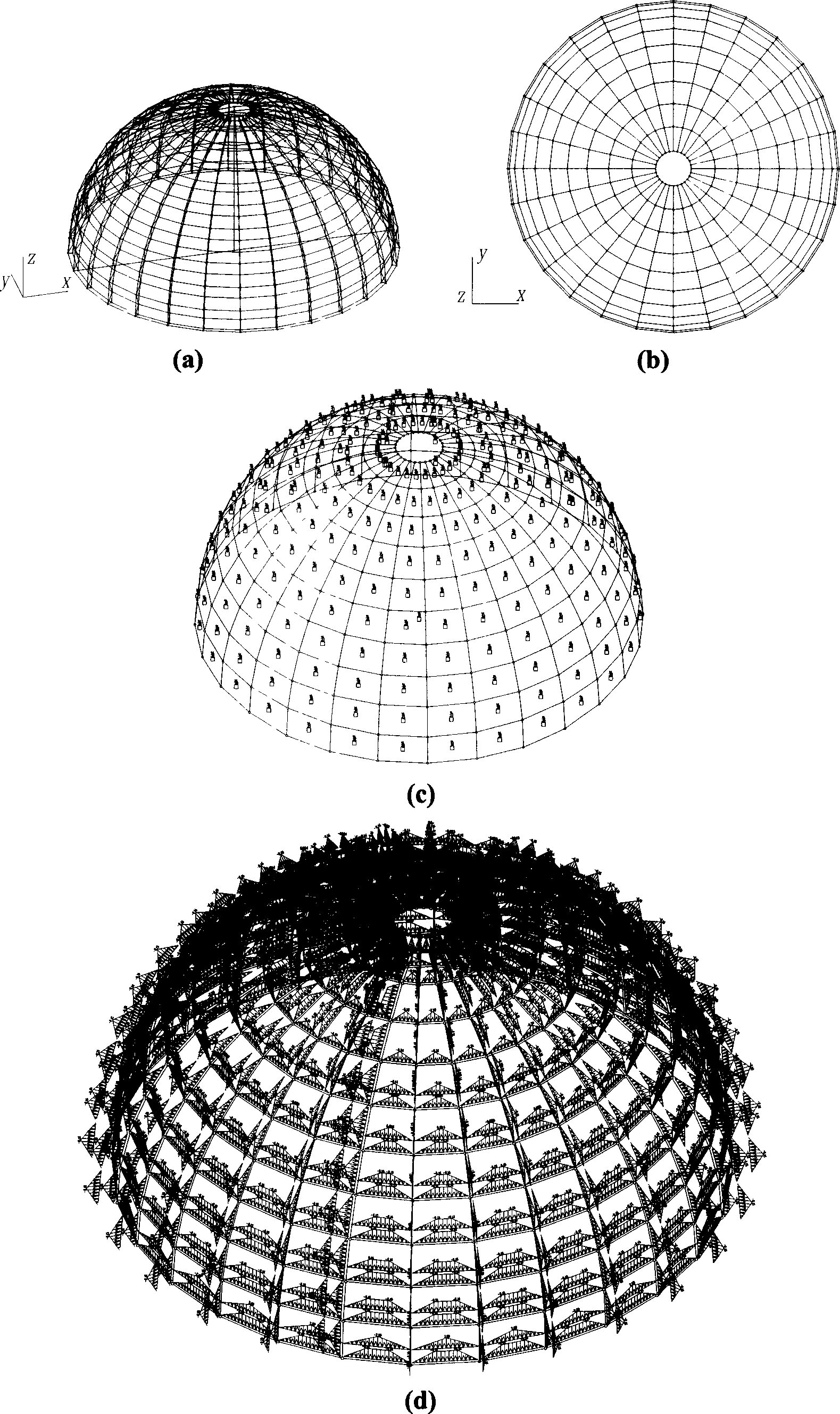
[0055] Such as figure 2 The dome structure shown in (a) is an observatory building with a circular arc truss structure. Surface distributed loads such as the self-weight of the panels, the maintenance load of the superior, and the wind load acting on the surface of the dome need to be derived to the upper chords of the arc trusses and the horizontal tie rods between the trusses as line loads.
[0056] Close the lower chord and web of the arc truss, and perform 3D view conversion (vertical top view), so that the outer surface of the dome is unfolded on the view projection plane, such as figure 2 (b) shown.
[0057] Using the method of the invention, all dome surface components are selected at one time, and a three-dimensional load grid in space and corresponding grid load units are formed according to the two-dimensional plane graphics on the view projection plane. And add the corresponding surface load value, direction, derived load mode and other parameters to the grid lo...
Embodiment 3
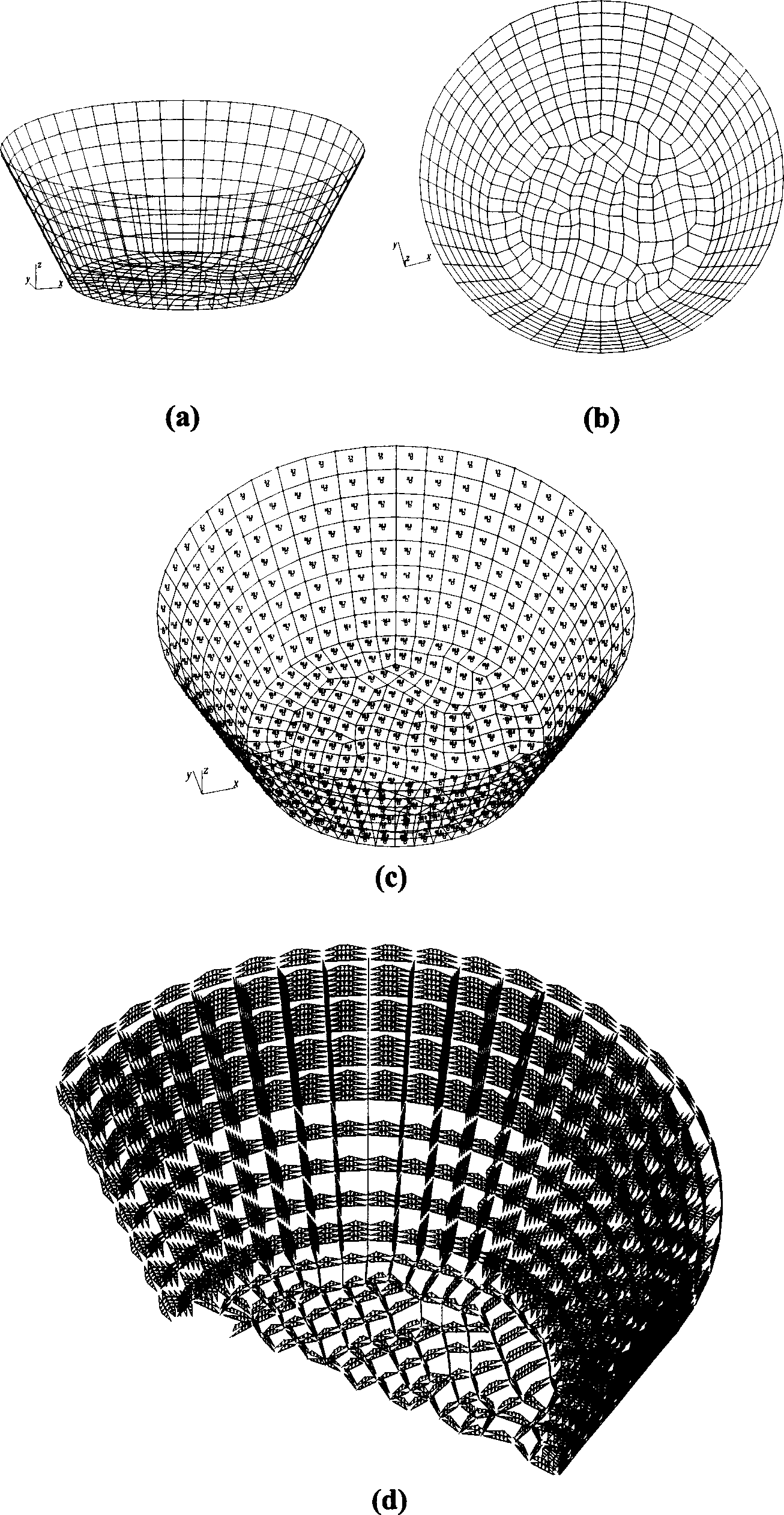
[0060] Such as image 3 The open circular pool shown in (a) adopts the structure type with slabs in the beams. It is necessary to derive the surface vertical water pressure inside the pool to the beams that make up the pool structure.
[0061] For 3D view conversion, the inner surface of the pool is unfolded on the view projection plane, such as image 3 (b) shown. By using the method of the invention, all components are selected at one time, and a three-dimensional load grid in space and corresponding grid load units are formed according to the two-dimensional plane graphics on the view projection surface. Use the software to apply the surface water pressure that varies along the height and is perpendicular to the grid plane to all the grid load elements at one time. Such as image 3 (c) shown.
[0062] The line load on the grid of the pool finally obtained in this embodiment is as follows: image 3 (d) Shown (partially).
[0063] As can be seen from the situation of t...
PUM
 Abstract
Description
Claims
Application Information