Base plate transfer device

A conveying device and substrate technology, applied in glass manufacturing equipment, glass transportation equipment, manufacturing tools, etc., can solve problems such as limited effect, delayed production, and inability to detect edge defects of glass substrates, saving space and avoiding pollution.

Inactive Publication Date: 2005-08-03
AU OPTRONICS CORP
View PDF0 Cites 12 Cited by
  • Summary
  • Abstract
  • Description
  • Claims
  • Application Information

AI Technical Summary

Problems solved by technology

[0003] (1) The edge defects of the glass substrate cannot be detected: such as Figure 1b As shown, since the area of ​​the supporting frame fork 100 is small, it cannot cover the edge of the enlarged glass substrate 200, so the crack defect 210 of the glass substrate cannot be effectively detected.
Moreover, such defects are usually particularly prone to appear on the edge of the glass substrate. If such a defective glass substrate is sent into the process machine, once it is broken, a large number of glass fragments will cause the machine to stop, delay production, and even worse. Can cause irreparable damage to the machine
[0004] (2) It is difficult to feed the glass substrate of the inclined loader

Method used


Image

  • Base plate transfer device
  • Base plate transfer device
  • Base plate transfer device

Examples


Example Embodiment

[0030] Example 1

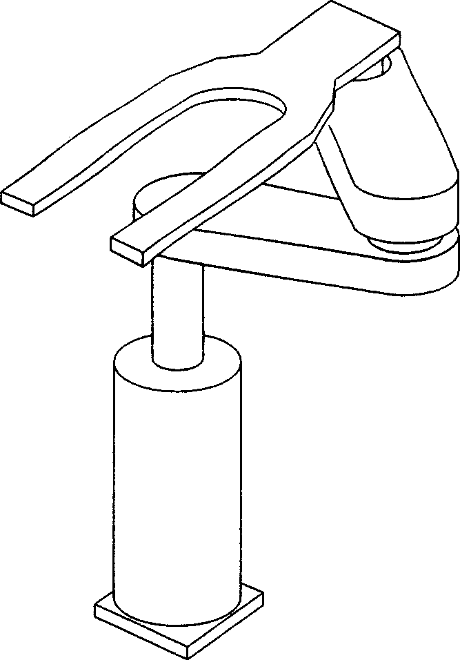
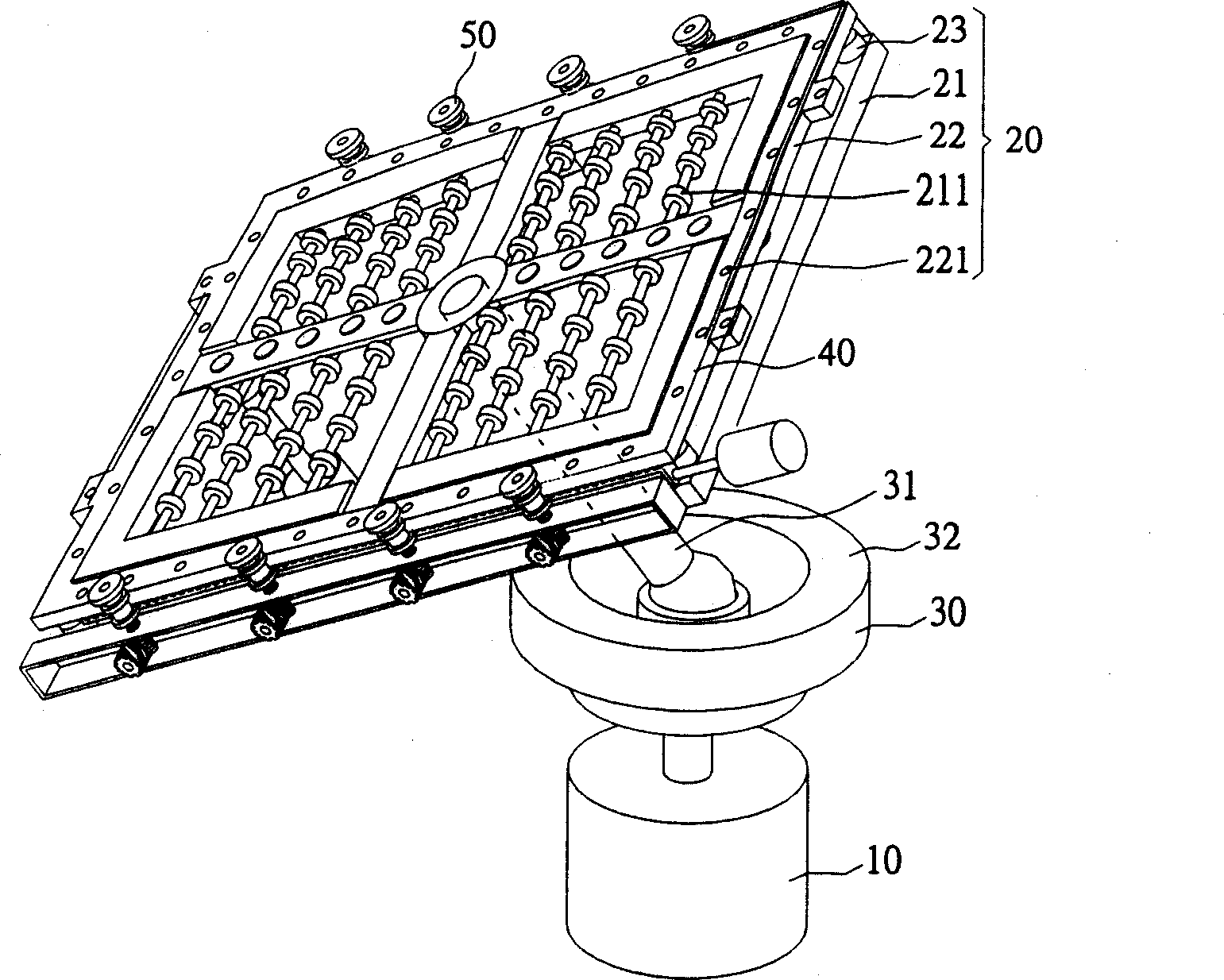
[0031] Please refer to figure 2 , figure 2 It is a combined perspective view of a preferred embodiment of the substrate transfer device of the present invention. The substrate transfer device of the present invention includes a base 10, a substrate carrying unit 20 and a rotating shaft unit 30. In this preferred embodiment, the base 10 may be a movable base, so that the substrate transfer device of the present invention can be moved to a desired position arbitrarily, or used to transport substrates. The rotating shaft unit 30 has a supporting shaft 31 and a rotating shaft seat 32. The lower end of the supporting shaft 31 is pivotally connected to the rotating shaft seat 32 to support and adjust the tilt direction and angle of the substrate carrying unit 20. The rotating shaft seat 32 is fixed on the base 10 to support and control the rotation of the support shaft 31 to indirectly control the tilt direction and angle of the substrate carrying unit 20. The sub...

Example Embodiment

[0033] Example 2

[0034] Please refer to FIG. 4, which is an exploded perspective view of a substrate carrying unit according to another preferred embodiment of the present invention. The structure of this preferred embodiment is roughly the same as that of Embodiment 1. The substrate carrying unit 60 includes a carrying base 61 connected to the supporting shaft 31, a plurality of supporting elements 611 located on the surface of the supporting base 61, and a supporting top base located on the upper side of the supporting element 611. 62. At least one retractable element 63 sandwiched between the supporting top base 62 and the supporting base 61, and a number of positioning elements 64, and the difference is that the supporting element 611 of the preferred embodiment is a pin. The retractable element 63 can be adjusted to pass through the supporting top base 62 to support the substrate. Similarly, the surface of the supporting top base 62 has several vacuum suction nozzles 621 ...

Example Embodiment

[0036] Example 3

[0037] Please refer to FIG. 5, which is an exploded perspective view of a substrate carrying unit according to another preferred embodiment of the present invention. The structure of this preferred embodiment is roughly the same as that of the second embodiment. The substrate carrying unit 70 includes a carrying base 71 connected to the supporting shaft 31, a carrying top seat 72 located on the upper side of the supporting base 71, and several supporting elements on the surface of the supporting base 71 711. At least one floating support element 721 installed in a floating manner inside the supporting top base 72, at least one telescopic element 73 sandwiched between the supporting top base 72 and the supporting base 71, and a plurality of positioning elements 74, and The difference is that the supporting element 711 of the present preferred embodiment is a protruding rod, which can be moved up and down by the adjustment of the retractable element 73 to push t...


PUM


Abstract

The base plate transfer device includes one pedestal; one rotation shaft unit with one support shaft and one rotation shaft seat fixed on the pedestal and pivoted with the support shaft to support the support shaft and control the rotation of the support shaft; and one base plate bearing unit fixed to the other end of the support shaft and including one bearing base connected to the support shaft, several bearing elements on the surface of the bearing base, one top bearing base on one side of the bearing elements and at least one telescopic element. The top bearing base has several vacuum sucking nozzles for sucking and detecting the base plate; the telescopic element is for regulating the interval between the top bearing base and the bearing base; and the rotation shaft seat controls the inclination of the base plate bearing unit indirectly. The present invention can detect the fault in base plate, correct the position of the base plate and convey base plate in inclined mode.

Description

【Technical field】 [0001] The invention relates to a substrate conveying device, in particular to a substrate conveying device suitable for large-size glass substrates. 【Background technique】 [0002] In the manufacturing process of liquid crystal display, its glass substrate needs to be transported through the conveying system between the place where the substrate is placed and the process machine, such as Figure 1a Shown is a conventional support frame fork (fork) and mechanical arm (robot) system. In recent years, in order to reduce the production cost of liquid crystal displays, the size of the glass substrate must be enlarged for the most effective and economical cutting. Therefore, the size of the glass substrate of the fifth-generation factory has already exceeded 2 meters. Furthermore, in order to cope with the large glass substrate, the way the glass substrate enters the processing tool has also changed. Most of the traditional glass substrates enter the machine in...

Claims


Application Information

Patent Timeline
IPC IPC(8): C03B35/14
Inventor 陈劲志李泰兴
Owner AU OPTRONICS CORP
Why Eureka
Try Eureka