Optical disk apparatus
A technology of optical disc devices and magnetic discs, which is applied in the direction of lasers, beam sources, optical recording heads, etc., and can solve the problems that optical pickups cannot be used
- Summary
- Abstract
- Description
- Claims
- Application Information
AI Technical Summary
Problems solved by technology
Method used
Image

Examples
no. 1 example =
[0054] ===First Embodiment===
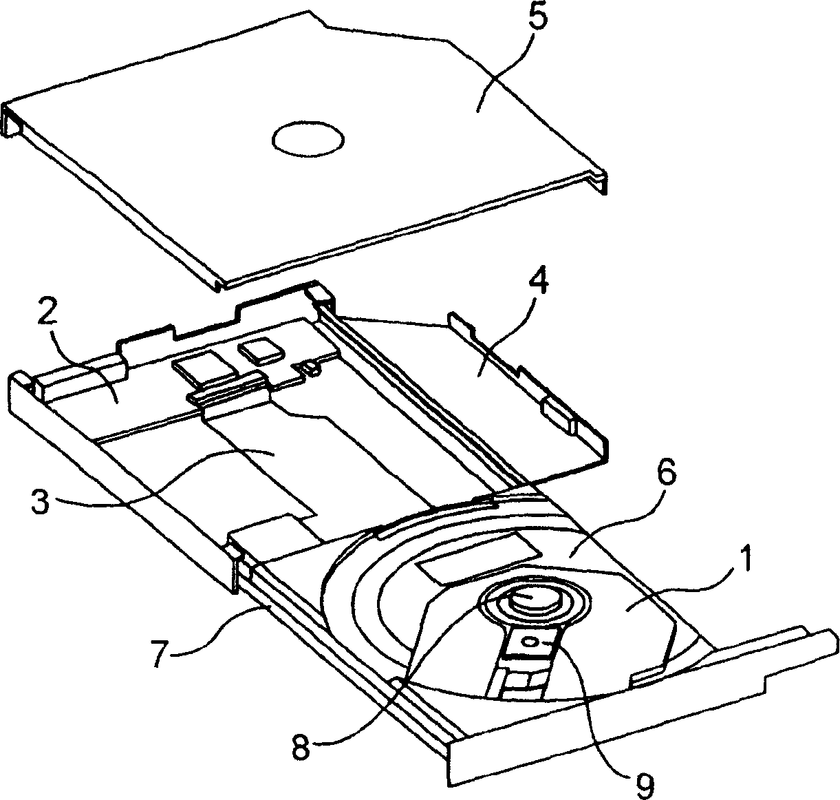
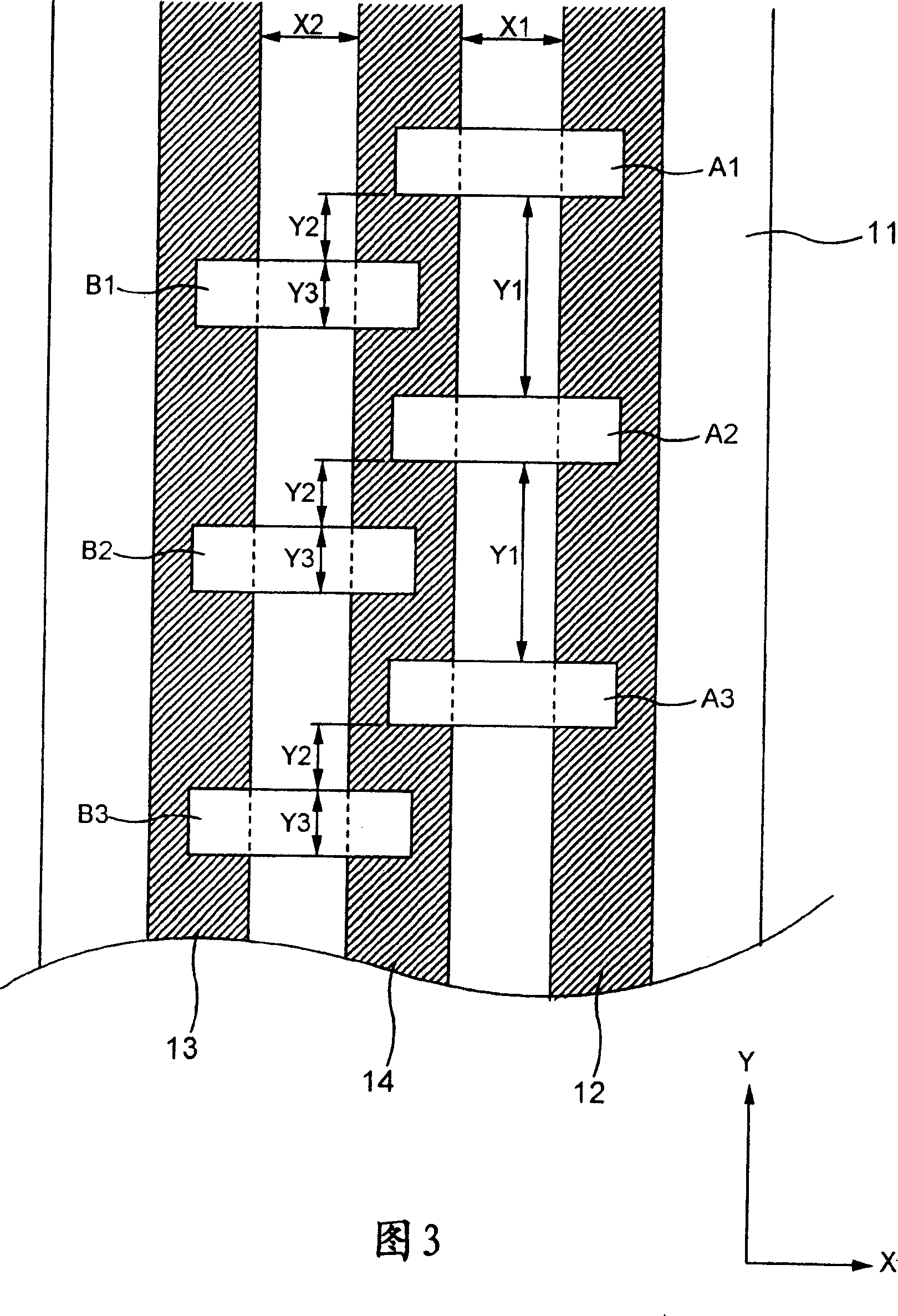
[0055] Fig. 3 shows a first embodiment of the invention. refer to figure 1 To 3, the specific details of short circuit and disconnection between the anode and cathode of the laser radiation equipment for CD and between the anode and cathode of the laser radiation equipment for DVD in the optical pickup 9 of the optical disc device of the present invention will be described. structure.
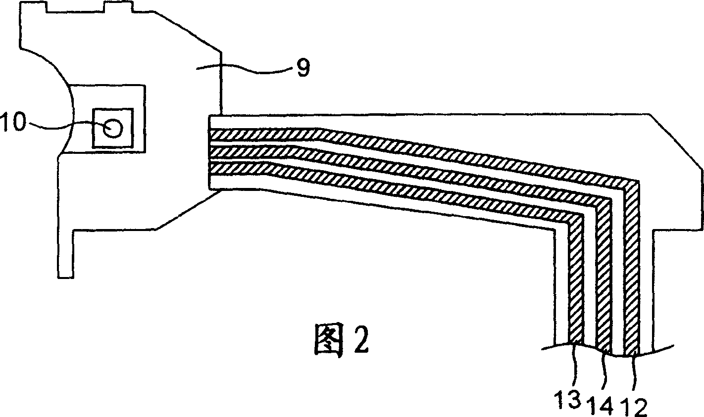
[0056] The lead board 11 is provided for electrically connecting the main circuit board 2 and the optical pickup 9 via the flexible printed board 3 . The lead wire 12 is connected to and extracted from, for example, the anode of the laser radiation device for CD, the lead wire 13 is connected to and drawn out from, for example, the anode of the laser radiation device for DVD, and the lead wire 14 is connected with (for example, at earth potential) of the laser radiation device for CD and DVD. For example, two cathodes are connected and drawn out. The lead wi...
no. 3 example =
[0078] ===Third Embodiment===
[0079] Figure 5 A third embodiment of the present invention is shown. refer to figure 1 , 2 and 5, the specific configurations of short circuit and disconnection between the anode and cathode of the laser radiation device for CD and between the anode and cathode of the laser radiation device for DVD in the optical pickup 9 of the optical disc device of the present invention will be described.
[0080] The lead board 11 is provided for electrically connecting the main circuit board 2 and the optical pickup 9 via the flexible printed board 3 . The lead wire 12 is connected to and extracted from, for example, the anode of the laser radiation device for CD, the lead wire 13 is connected to and drawn out from, for example, the anode of the laser radiation device for DVD, and the lead wire 14 is connected with (for example, at earth potential) of the laser radiation device for CD and DVD. For example, two cathodes are connected and drawn out. Th...
no. 4 example =
[0090] ===Fourth Embodiment===
[0091] Fig. 6 shows a fourth embodiment of the present invention. refer to figure 1 , 2 and 6, the specific configurations of short circuit and disconnection between the anode and cathode of the laser radiation device for CD and between the anode and cathode of the laser radiation device for DVD in the optical pickup 9 of the optical disc device of the present invention will be described.
[0092] The lead board 11 is provided for electrically connecting the main circuit board 2 and the optical pickup 9 via the flexible printed board 3 . The lead wire 12 is connected to and extracted from, for example, the anode of the laser radiation device for CD, the lead wire 13 is connected to and drawn out from, for example, the anode of the laser radiation device for DVD, and the lead wire 14 is connected with (for example, at earth potential) of the laser radiation device for CD and DVD. For example, two cathodes are connected and drawn out. The lea...
PUM
 Abstract
Description
Claims
Application Information
 - Generate Ideas
- Intellectual Property
- Life Sciences
- Materials
- Tech Scout
- Unparalleled Data Quality
- Higher Quality Content
- 60% Fewer Hallucinations
Browse by: Latest US Patents, China's latest patents, Technical Efficacy Thesaurus, Application Domain, Technology Topic, Popular Technical Reports.
© 2025 PatSnap. All rights reserved.Legal|Privacy policy|Modern Slavery Act Transparency Statement|Sitemap|About US| Contact US: help@patsnap.com