Helirota plane

A rotorcraft and rotor technology, applied in the field of aviation aircraft, can solve the problems of low efficiency, complex power system, and small pitch adjustment range of high efficiency, so as to reduce wear and fatigue loss, wide pitch adjustment range, and improve flight safety Effect

Inactive Publication Date: 2005-08-10
章洪
View PDF0 Cites 9 Cited by
  • Summary
  • Abstract
  • Description
  • Claims
  • Application Information

AI Technical Summary

Problems solved by technology

This aircraft has combined traditional helicopter and traditional rotorcraft, and it partially solves the respective deficiencies of traditional helicopter and traditional rotorcraft, but it also has disadvantages: 1. This aircraft will use two different engines, making it The power system is relatively complicated; 2. Its two engines use different fuels, which are not compatible with each other, which increases the restrictions on its own flight; 3. When cruising, it uses negative twist propellers and negative pitch blades for positive Working in the range of torsion and negative pitch reduces the aerodynamic efficiency of the rotor during cruising flight; 4. The aircraft can only use the maneuvering method of a helicopter for maneuvering flight
[0007] The pitch control blade of the above-mentioned helicopter is formed by changing the fixed paddle shaft of the ordinary fixed pitch blade to the pitch adjustment shaft. The disadvantage of this pitch control blade is that the efficient working range of the pitch is small, and the entire The blades all rotate at the same angle, and it can work efficiently only when the pitch is set; when it is adjusted to deviate from the optimum value, only a certain section of the blade has high efficiency, and the installation angle error of other parts increases, and the efficiency is significantly reduced
Due to the deficiency of existing pitch control blades, the development of various aircrafts utilizing pitch control blades is limited
[0008] A kind of existing rotor with servo flap 16 (see Figure 8 ), its torsion is fixed to the traditional blade, and its torsion cannot be adjusted; the servo flap 16 is used to adjust the lift of the rotor, which cannot change the basic characteristics of its blade as negative torsion, and its high-efficiency pitch adjustment range is small
[0009] State-of-the-art non-twisting propellers, which are only used for scientific research, it has never been used in any practical aircraft

Method used


Image

  • Helirota plane
  • Helirota plane
  • Helirota plane

Examples


Embodiment 1

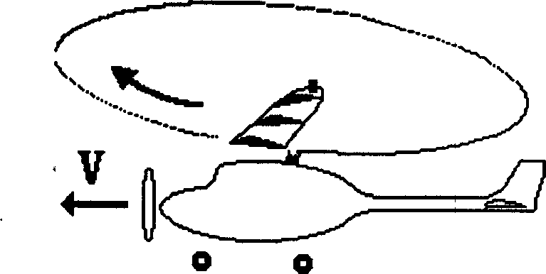
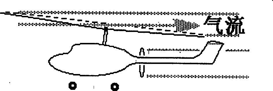
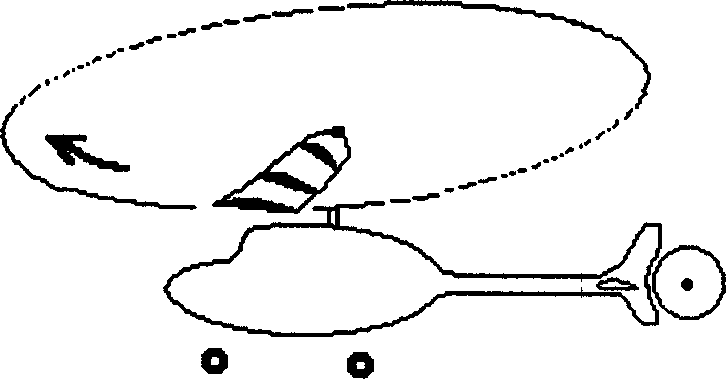
[0104] See Fig. 10,11,12,13-2, a kind of novel rotorcraft of intersecting double-rotor aerodynamic structure, it comprises fuselage 5, conventional helicopter power system, the main shaft 2 of fuselage upper part and the horizontal drive propeller 3 of rotorcraft, Drive clutch 15, empennage 4 etc. horizontally. The output end of the conventional helicopter power system is the main shaft 2, the upper end of the main shaft 2 is connected to the rotor 1, and the rotor 1 adopts a twist pitch propeller, which can be adjusted from positive pitch and negative twist to negative pitch and positive twist; the twist pitch propeller is as follows: Figure 13-2 Shown, be made up of variable torsion paddle 43, paddle shaft 26, adjustment bar 27. Figure 12 As shown, this machine can utilize the engine 13 in the conventional helicopter power system to drive the rotor 1 with positive pitch on the upper end of the main shaft 2 through the output shaft 12 through the main clutch 14 and the fina...

Embodiment 2

[0110] See Figure 16-1 , 16-2 , 17, 18, 19, 20, the above-mentioned aerodynamic variable torsion propeller, its blade tip 43b is additionally provided with an auxiliary wing, and its auxiliary wing is an aerodynamic variable torsion propeller using tip flaps, the aerodynamic variable torsion propeller Compared with "Example 1", there are more variable torque groups, and other parts are the same as "Example 1".

[0111] The auxiliary wing uses the aerodynamic twist propeller of the blade tip flap. The purpose is: 1. When it is working in the cruising state, it can control the lift of the blade tip more accurately, and the torque generated by the lift force is smaller than the twisting of the blade. degree (see Figure 17 shown in B' in). 2. During power vertical take-off and landing, the blade tip flaps added to the blade tip 43b should be used to increase the lift of the blade tip and obtain sufficient negative torque, so that the blade main part 43a is negatively twisted ...

Embodiment 3

[0115] See Figure 21 , the above-mentioned torsion pitch propeller, its auxiliary wing can use a kind of adaptive wing of prior art, in order to change the aerodynamic angle of attack of this adaptive wing. Other parts are the same as "Example 2".

[0116] The adaptive auxiliary wing can also well complete the same function as the blade tip flap in "Embodiment 2".


PUM


Abstract

A rotor craft able to vertically take off and land is composed of main body, mainshaft, rotor fixed to mainshaft and with the adjustable torsional blades, horizontally driving clutch, power system, rear fin and propeller for horizontally driving. Its advantages are flexibly taking-off and landing, high safety and low noise.

Description

technical field [0001] The invention belongs to an aviation aircraft, in particular to a helicopter rotorcraft. Background technique [0002] The traditional rotorcraft is driven forward by the horizontal drive of the front or rear propeller of the fuselage, see figure 1 , figure 2 , (the arc arrow in the plane of rotor rotation in the figure indicates the direction of rotor rotation, figure 1 Briefly shows the cross-sectional view of a blade and its three cross-sectional positions, the following image 3 , Figure 5 also the same). The gyroplane flies forward at speed V; figure 1 Pull-in propeller shown, figure 2 Pusher propeller shown. The airflow horizontally passes through the rotor rotation plane at a certain speed to drive the rotor to rotate at high speed, so that the rotor can gain lift and fly, and the blades are in negative pitch and positive torsion working state. After the airflow passes through the rotor, the air wake is basically parallel to the headi...

Claims


Application Information

Patent Timeline
Patent Type & Authority Applications(China)
IPC IPC(8): B64C11/32B64C27/02B64C27/54
CPCB64C27/025
Inventor 章洪
Owner 章洪
Why Eureka
Try Eureka