Direct driving type belt conveyer

A belt conveyor, direct drive technology, applied in the direction of conveyor, transportation and packaging, etc., can solve the problems of troublesome speed regulation and control, high investment cost, high operating cost, etc., to improve efficiency, reduce operating cost, and occupy an area little effect

Inactive Publication Date: 2005-08-10
ZHEJIANG UNIV +1
View PDF0 Cites 5 Cited by
  • Summary
  • Abstract
  • Description
  • Claims
  • Application Information

AI Technical Summary

Problems solved by technology

In addition, their speed regulation and control are cumbersome
Generall

Method used


Image

  • Direct driving type belt conveyer
  • Direct driving type belt conveyer
  • Direct driving type belt conveyer

Examples


Embodiment Construction

[0026] Further description will be made below in conjunction with the embodiments and accompanying drawings.

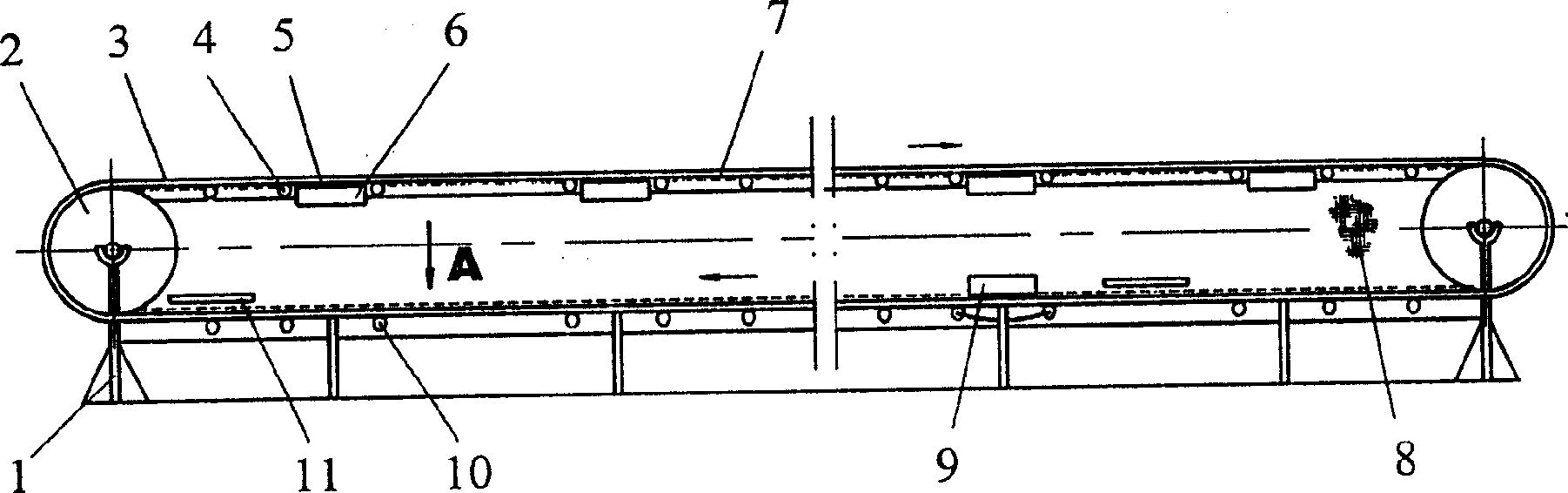
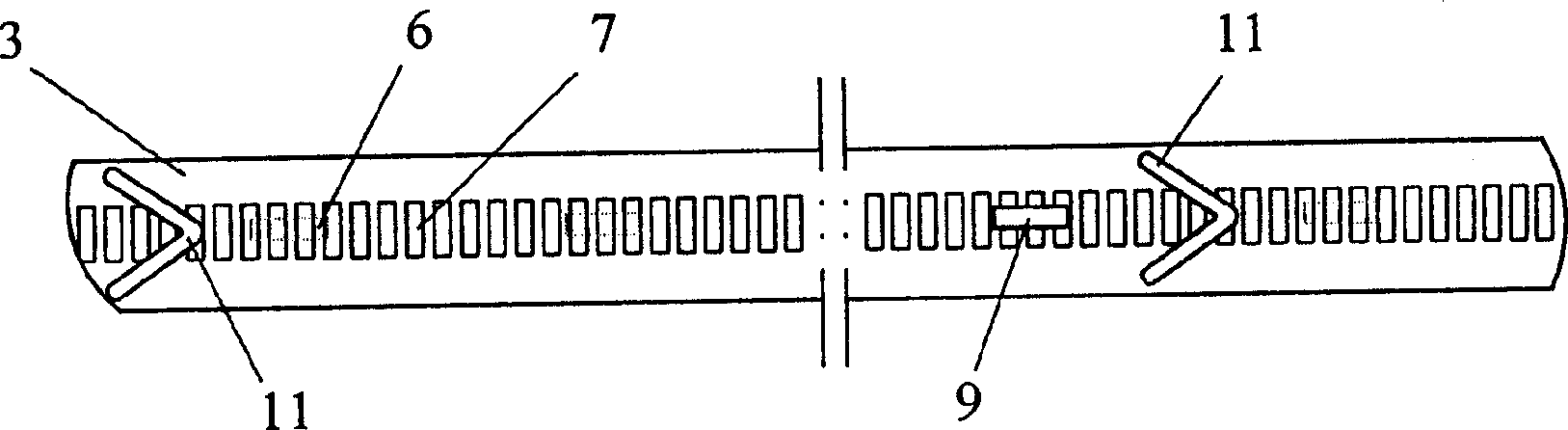
[0027] See attached figure 1 . This is a basic structural diagram of an embodiment of a direct drive belt conveyor. It includes a bracket 1, a roller 2, a conveyor belt 3, a roller 4, a power motor and its control device, and it is characterized in that the motor is a linear motor 6, and the body of the linear motor and its primary are distributed along the centerline of the conveyor belt and the roller They are installed together on the bracket; the secondary 7 corresponding to the primary is installed on the inner side of the endless conveyor belt, and the secondary plates are horizontally arranged in an intermittent and closed arrangement along the longitudinal direction of the conveyor belt. 5 represents the conveyor belt running gap positioning wheel. The 8th, be located at support both sides, make the wallboard or guard net that lateral enclosure usefulness. ...


PUM


Abstract

The invention discloses a material conveying device driven by a linear motor, which comprises a supporting frame (1), drums (2), a conveying belt (3), supporting rollers (4), a linear motor and a controller. It features that the primary windings of the linear motor (6) are arranged along the central line of the conveying belt and are installed on the supporting frame (1) together with the supporting rollers (4). The secondary windings (7) of the linear motor (6), corresponding to the primary windings, are arranged on the inside surface of the annular conveying belt. Secondary plates are transversely arranged along the longitudinal direction of the conveying belt discontinuously in a closed arrangement. The material conveying device effectively reduces the cost and is in favor of automatic monitoring, control, maintenance and management. Meanwhile, the device is uniform in force distribution and stable in operation, which is especially suitable for the long-distance material conveying operation.

Description

technical field [0001] The present invention belongs to conveying device. In particular, it can be used as a conveying mechanism for long-distance conveying materials. Background technique [0002] The conveying operation line in the prior art is composed of one or more than one conveyors. A rotating motor is used to drive the rollers, and the rollers drive the conveyor belt to run, and the materials loaded on the belt are transported from one end to the other end. Transported from one place to another. They need to build stations in sections for transit during transportation. According to the computer room with an area of ​​100 square meters per kilometer, a computer room of 2,400 square meters will be built at a distance of 12 kilometers. In addition to being equipped with a high-power machine, each machine room also has a complex and huge reducer. In addition, their speed regulation and control are cumbersome. Generally speaking, its inves...

Claims


Application Information

Patent Timeline
IPC IPC(8): B65G15/30
Inventor 叶云岳
Owner ZHEJIANG UNIV
Why Eureka
Try Eureka