
Transformer core laminating method

A transformer and iron core technology, applied in the field of transformer core laminations, can solve problems such as uneven distribution of core magnetic flux density, affecting reliable operation of products, transformer iron loss and no-load current increase

Inactive Publication Date: 2005-08-17
TEBIAN ELECTRIC APP CO LTD
View PDF0 Cites 3 Cited by
  • Summary
  • Abstract
  • Description
  • Claims
  • Application Information

AI Technical Summary

Problems solved by technology

However, the disadvantage of this lamination method is that the magnetic flux density distribution of each part of the iron core is not uniform, which will lead to the increase of transformer iron loss and no-load current, and affect the reliable operation of the product.

Method used


Image

  • Transformer core laminating method

Examples


Embodiment approach

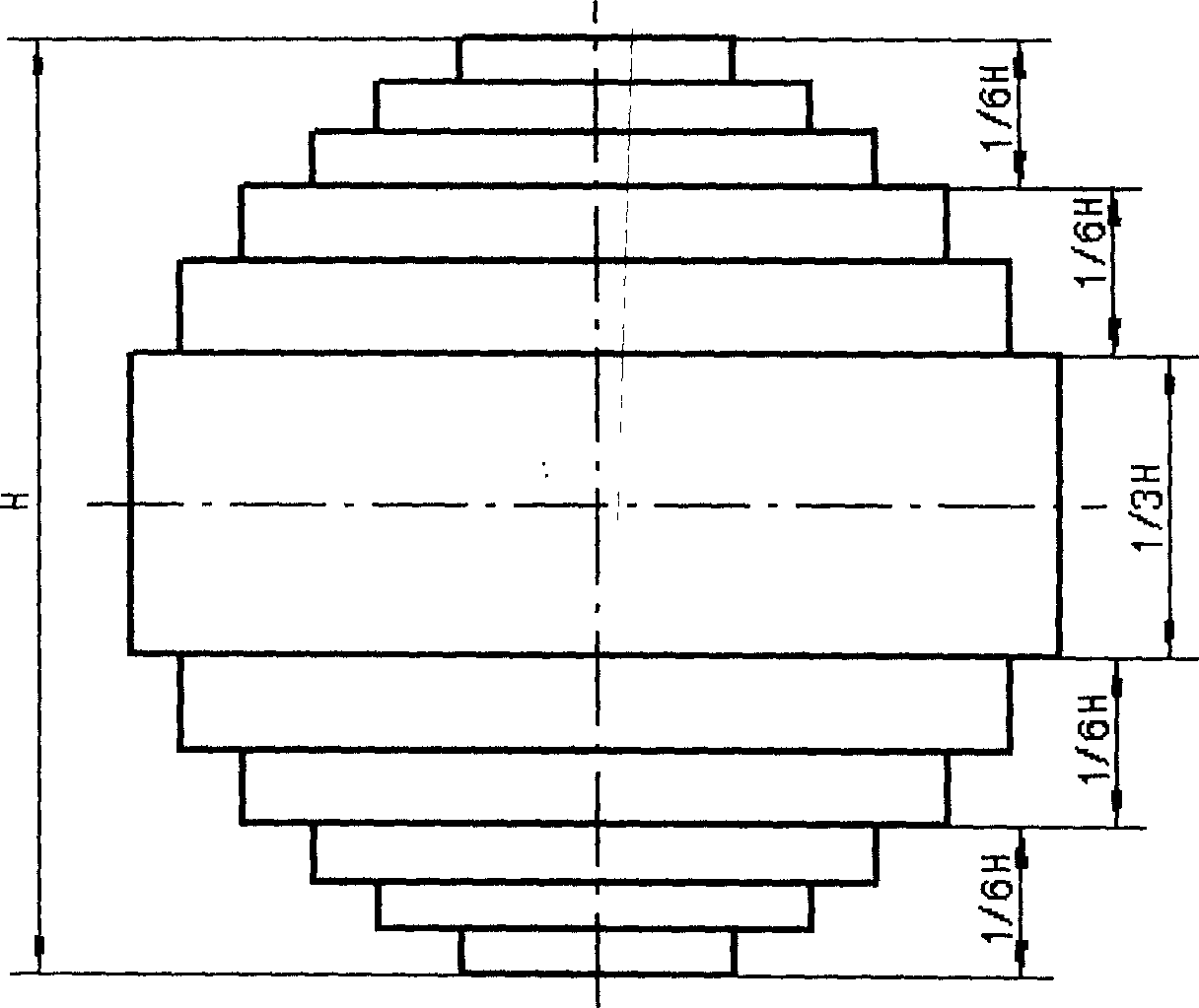
[0009] The invention relates to a method for stacking iron cores of a transformer, which is an organic combination of a one-piece stacking method, a two-piece stacking method and a three-piece stacking method. combine as figure 1 To explain in detail, the thickness of the core column is roughly divided into five parts. The total stacked thickness of the core is H, which is 1 / 6H, 1 / 6H and 1 / 3H from both sides to the middle. Among them, the two outermost parts of about 1 / 6H of the core column adopt the method of three-piece stacking, the two parts near the middle of about 1 / 6H adopt the method of two-piece stacking, and the middle part of about 1 / 3H adopts the method of stacking A stacked approach.

[0010]


PUM


Abstract

This invention relates to transformer iron core slice iterated method, which combines the one-slice iterated method and two and three slice iterated method organically. The invention is characterized by the following: adopting one-slice iterated method at the one sixth of the thickness of the iron column; adopting two-slice iterated method at the one sixth of the thickness of the iron column; adopting three-slice iterated method at the one third of the thickness of the iron column

Description

Technical field: [0001] The invention relates to an iron core lamination method of a transformer, which is especially suitable for the iron core lamination method of small and medium-sized transformer products. Background technique: [0002] In the transformer industry, the thickness of the transformer core is stacked up by layers of core sheets. Theoretically speaking, it is best to adopt the method of stacking one piece per layer. The method of stacking one piece is to adopt the method of stacking one core piece per layer at each level of the stacked core, but this method is not suitable for small and medium-sized It is not suitable for transformer production, because small and medium-sized transformer products are generally produced in large quantities, and the method of stacking one piece will increase the workload of stacking, increase a large number of operating hours, and the efficiency is too low. Therefore, in the actual production process, small and medium-sized t...

Claims


Application Information

Patent Timeline
Patent Type & Authority Applications(China)
IPC IPC(8): H01F41/02
Inventor 马云腾李佩福
Owner TEBIAN ELECTRIC APP CO LTD
Learn More