

Electronic watermark embedded device and method and electronic watermark pick up device and method
A technology for electronic watermarking and embedding devices, which is applied to secure communication devices, encoding/decoding devices, electrical components, etc., and can solve problems such as being unsuitable for static images.
- Summary
- Abstract
- Description
- Claims
- Application Information
AI Technical Summary
Problems solved by technology
Method used
Image

Examples
no. 1 approach
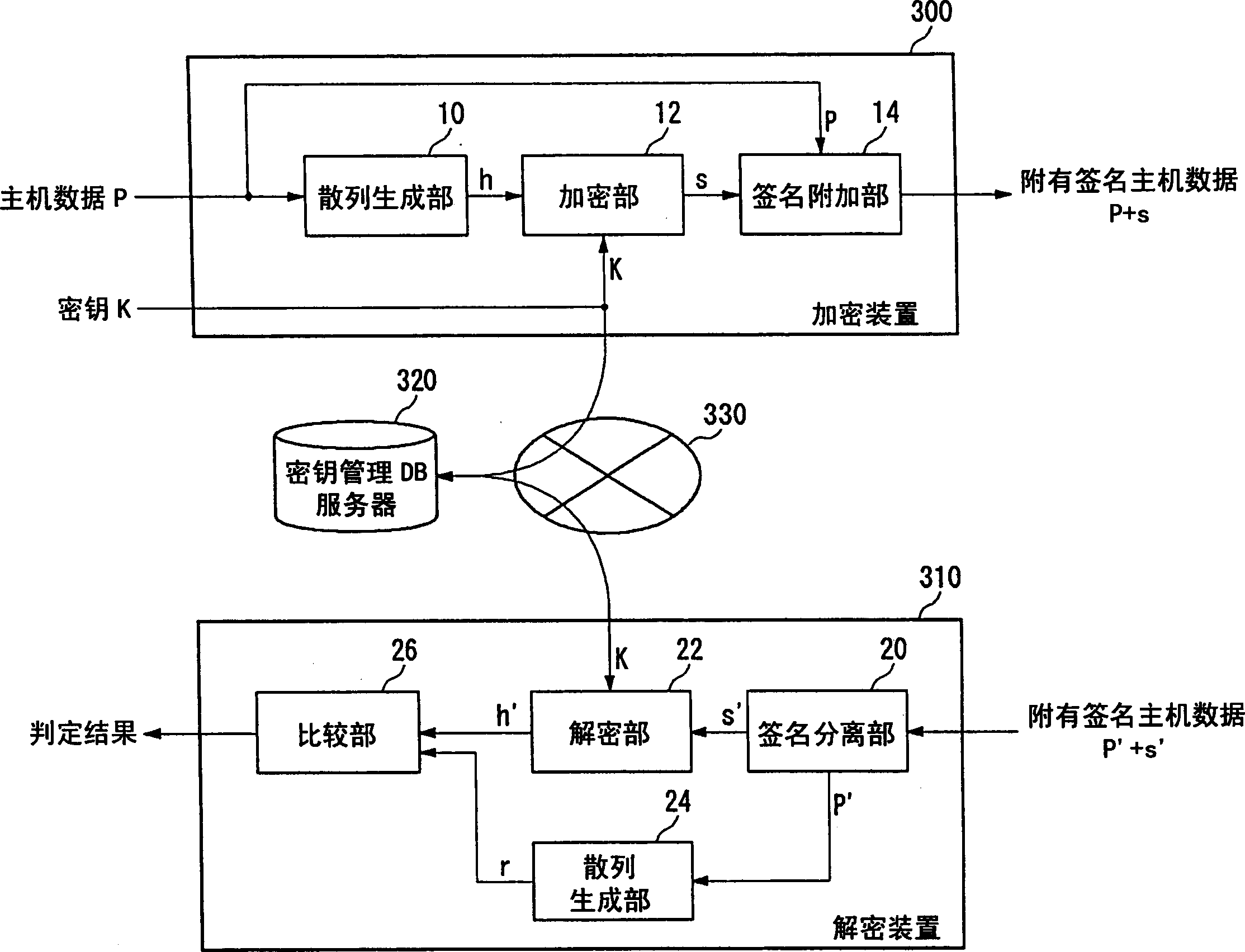
[0063] The tamper detection system related to the first embodiment includes figure 2 The watermark embedding device 100 and Figure 4 The watermark extraction device 200. These devices are connected through a network, and the data output by the watermark embedding device 100 is input to the watermark extraction device 200 via the network. Alternatively, a system may be used in which the watermark embedding device 100 is used as a server and the watermark extraction device 200 is used as a client. In addition, these devices may be integrated as one device, and the data output by the watermark embedding device 100 may be stored in the storage device, or the data read from the storage device may be input to the watermark extraction device 200 .
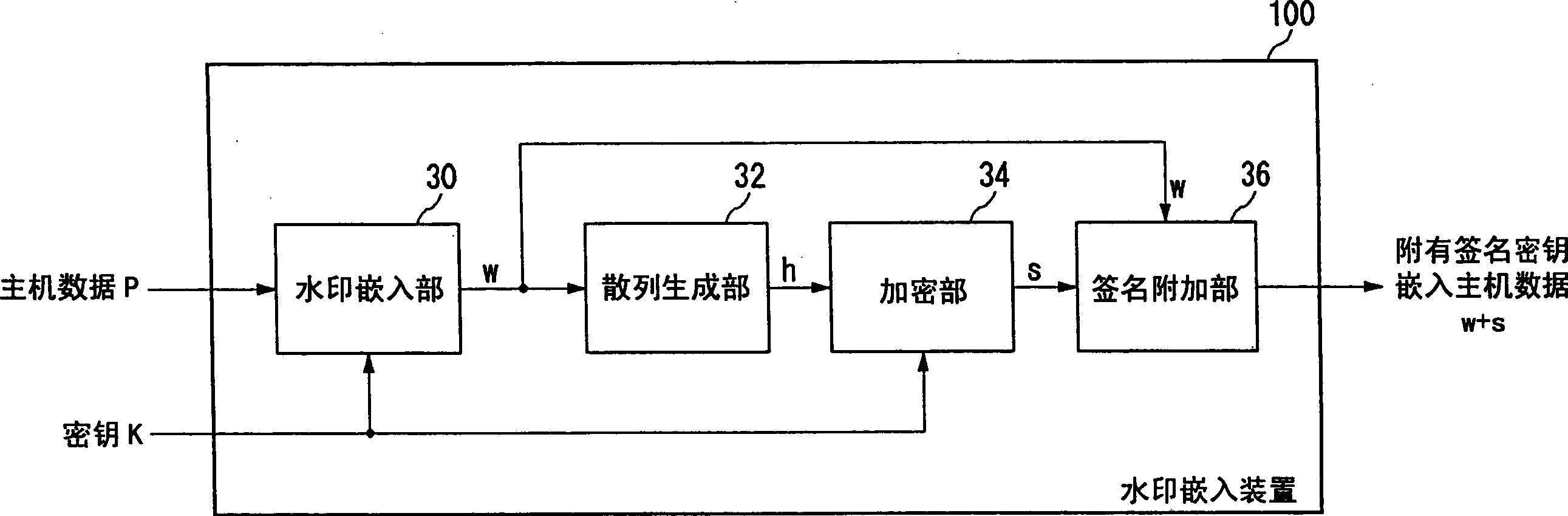
[0064] figure 2 It is a configuration diagram of the watermark embedding device 100 according to the first embodiment. This configuration can be realized in hardware by using the CPU, memory, and other LSIs of any computer, and in ...
no. 2 approach
[0083] The falsification detection system of the second embodiment is also the same as the first embodiment, and although it includes the watermark embedding device 100 and the watermark extraction device 200 , the configuration of the watermark extraction device 200 is different. The watermark embedding device 100 is the same as the first embodiment, so its description will be omitted.
[0084] Image 6 It is a configuration diagram of the watermark extraction device 200 according to the second embodiment. The signature separation unit 40 separates and extracts the key-embedded host data w' and the electronic signature s' from the input signature key-embedded host data w'+s', and gives the key-embedded host data w' to the watermark extraction unit respectively. 44 and the hash generation unit 46 give the electronic signature s′ to the comparison unit 48.
[0085] The watermark extraction unit 44 extracts the key K′ embedded in the key embedding host data w′ as a digital wat...
no. 3 approach
[0090] The falsification detection system according to the third embodiment also includes the watermark embedding device 100 and the watermark extraction device 200 as in the first embodiment, but the configuration of the watermark embedding device 100 is different. The description of the watermark extraction device 200 is omitted because it is the same as the first embodiment, regardless of the influence of the watermark on the hash.
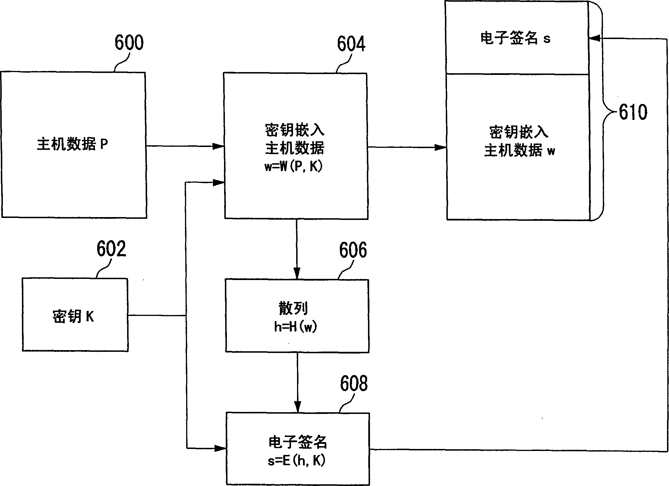
[0091] Figure 8 It is a configuration diagram of the watermark embedding device 100 according to the third embodiment. The watermark embedding device 30 embeds the key K as a digital watermark in the input host data P to generate the key embedding host data w, and gives it to the signature adding unit 36 .
[0092] The hash generator 32 uses a one-way function to map the host data P, generates a hash h, and gives it to the encryption unit 34 . In the first embodiment, the hash generation unit 32 uses a one-way function to map the key-embed...
PUM
 Abstract
Description
Claims
Application Information