The electric arc spraying device

A technology of arc spraying and supplying device, which is applied in the direction of fusion spraying, metal material coating process, coating, etc., which can solve the problems of increased conveying resistance, limited guide tube length, inability to work efficiently, etc., to achieve arc spraying stable effect

Inactive Publication Date: 2005-09-07
DAIHEN CORP
View PDF1 Cites 4 Cited by
  • Summary
  • Abstract
  • Description
  • Claims
  • Application Information

AI Technical Summary

Problems solved by technology

In this case, during the on-site construction, the operator operates the coating gun by hand, and the wire supply device is frequently moved, so efficient work cannot be performed.
[0013] As a result, the length of the guide tube is limited due to the conveying force of the push conveying part and the stretching conveying part
In addition, in the case where the guide tube is bent due to the operating posture, the length of the guide tube is further restricted due to the increased conveyance resistance exerted on the sprayed wire
[0014] Therefore, in the above-mentioned prior art arc spraying apparatus, for example, when a guide pipe longer than 10 m is required, the sprayed wire cannot be conveyed at a constant speed, and a uniform sprayed film cannot be formed.

Method used


Image

  • The electric arc spraying device
  • The electric arc spraying device

Examples


Embodiment Construction

[0023] Hereinafter, embodiments of the invention will be described based on examples with reference to the drawings.

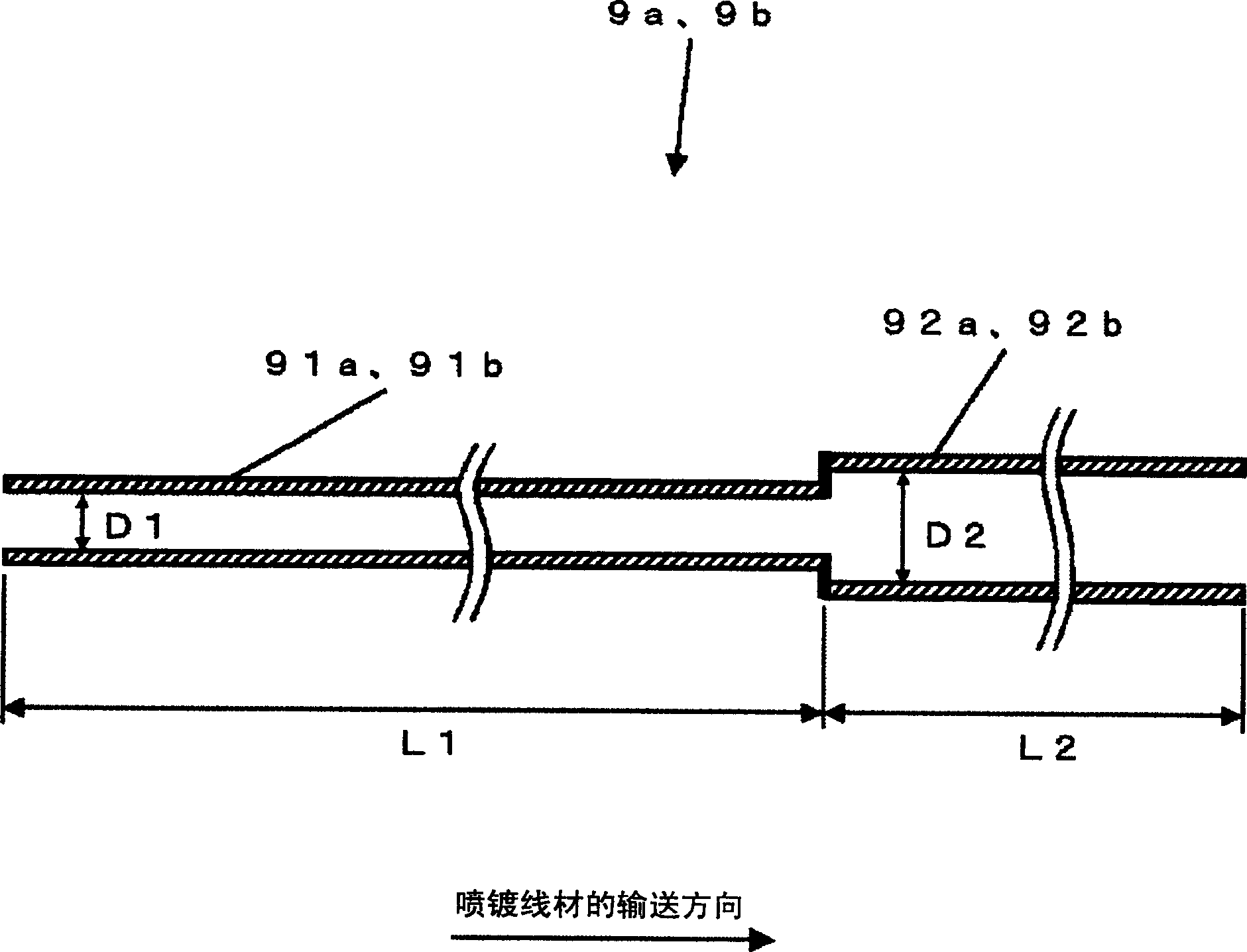
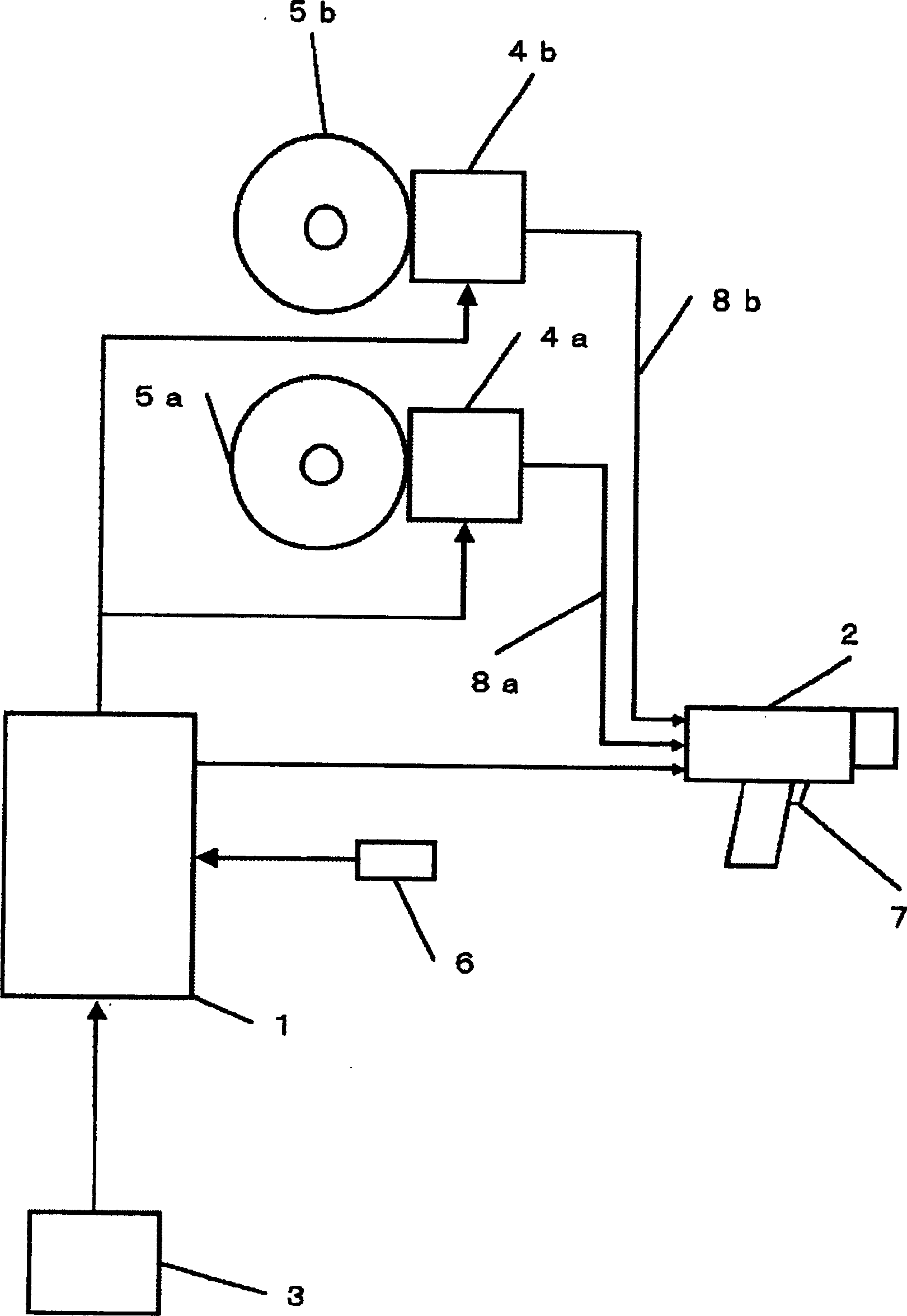
[0024] figure 1 It is a cross-sectional view of a guide pipe for conveying two sprayed wires between the wire supply device and the spray gun in the arc spraying apparatus of the present invention. In this figure, the guide tubes 9a, 9b are not used figure 2 The shown prior art guide tubes 8a, 8b are made of a flexible material that does not expand or contract in the axial or radial direction. will be from figure 2 The inner diameter D1 of the connection side of the two wire supply devices 4a, 4b shown in the predetermined length to the pushing side pipe 91a, 91b is made into a normal inner diameter with a small difference between the outer diameter of the sprayed wire rod and the inner diameter of the guide pipe. In addition, the inner diameter D2 of the drawing side pipes 92a, 92b from the tip of the pushing side pipes 91a, 91b to the connection side of ...


PUM


Abstract

The purpose of this invention is to provide an electric arc spraying device where thermal spraying wire rods can be fed always at fixed speed, thus uniform spray deposit can be formed. In the electric arc spraying device provided with wire rod feeders having push feed parts of feeding both thermal spraying wire rods, a thermal spraying gun having a pull feed part of relaying both the thermal spraying wire rods fed from the wire rod feeders, feeding them to the object to be thermal-sprayed, and performing electric arc spraying: and guide tubes of guiding the feed of both the thermal spraying wire rods between each wire rod feeder and the thermal spraying gun, each guide tube has an ordinary inside diameter from the connection side to each wire rod feeder to a prescribed length and has an inside diameter larger than the ordinary one therefrom to the connection side to the thermal spraying gun.

Description

technical field [0001] The present invention relates to an improved arc spraying apparatus for effective spraying in the rust and corrosion protection of electrical equipment, large steel components, and the like. Background technique [0002] Arc spraying is a spraying method in which two sprayed wires are respectively supplied to the contact piece of a spraying gun, an electric arc is generated between the tips of the two sprayed wires by the spraying gun, and the heat of the arc Melting and spraying the wire rod according to its melting speed, while supplying the spraying wire rod according to the melting speed, the molten metal is miniaturized by spraying compressed gas or the like, and sprayed on the workpiece to form a sprayed coating film. [0003] figure 2 It is a configuration diagram showing a conventional arc spraying device. In this figure, a thermal spraying power supply device 1 uses a commercial power supply as an input, and its output is controlled by an in...

Claims


Application Information

Patent Timeline
Patent Type & Authority Applications(China)
IPC IPC(8): C23C4/12
Inventor 有坂宏平辻井元
Owner DAIHEN CORP
Why Eureka
Try Eureka