
Method for manufacturing metal outer frame for panel display

A flat-panel display, metal frame technology, applied in metal casings, manufacturing tools, metal processing equipment, etc., can solve problems such as increased processing costs, alarming costs, and material waste.

Inactive Publication Date: 2005-09-14
CHI LIN TECH CO LTD
View PDF0 Cites 20 Cited by
  • Summary
  • Abstract
  • Description
  • Claims
  • Application Information

AI Technical Summary

Problems solved by technology

[0010] The disadvantages of this traditional process are as follows: since the metal frame 1 is integrally formed, in addition to the stamping machine, the required molds and jigs must be roughly equal in size to the metal frame 1 during the stamping process. It is also difficult to design similar molds. With the increasing demand for panel sizes, the cost of providing stamping machines, molds, and fixtures that meet this process will be quite astonishing, and will also greatly increase processing. cost
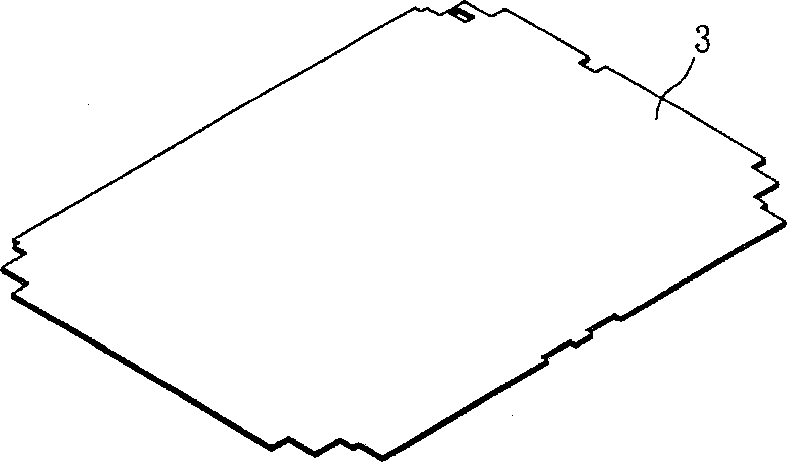
Additionally, if Figure 2e In the middle punching step shown, a large area of ​​waste material 31 must be washed away in the middle of the plate 3, which causes a waste of material, and when the area of ​​the metal outer frame 1 is larger, the area of ​​the waste material 31 is also insignificant. Inevitably ensues, which will undoubtedly increase material costs

Method used


Image

  • Method for manufacturing metal outer frame for panel display
  • Method for manufacturing metal outer frame for panel display
  • Method for manufacturing metal outer frame for panel display

Examples


Embodiment Construction

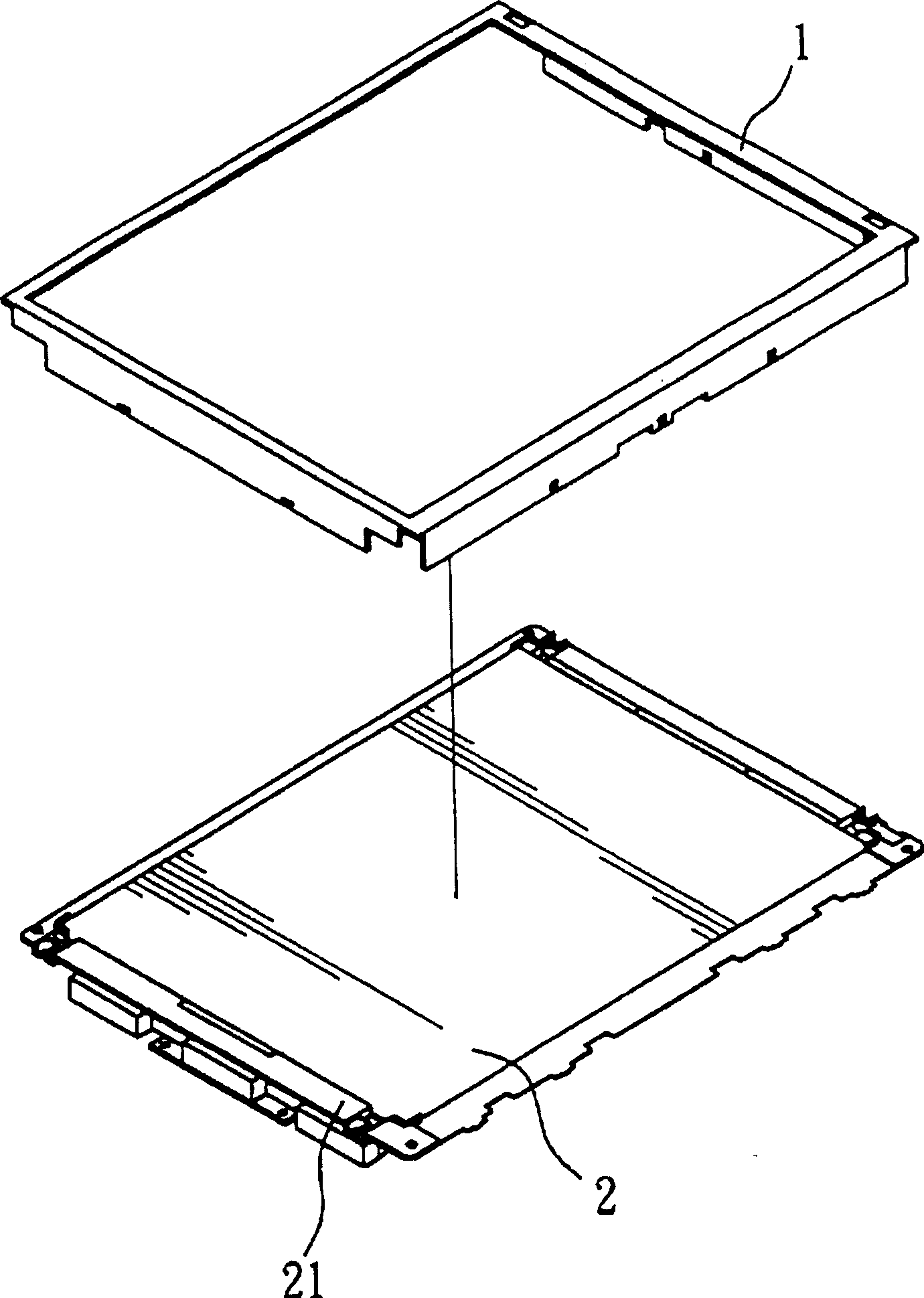
[0021] refer to Figure 3a to Figure 3e , which shows a method of manufacturing a metal frame according to a preferred embodiment of the present invention. In this example, the purpose of the metal frame is the same as figure 1 The same figure is used to fix a backlight module of a flat panel display, but in other applications, the metal frame can also be used to fix a display panel or other components of a flat panel display. In addition, in this embodiment, the overall structure of the metal frame is the same as figure 1 As shown, it is roughly the same, except that it has to use a completely novel manufacturing method to achieve the purpose of saving material and processing costs.

[0022] refer to Figure 3a , first provide a plurality of plates 5 as raw materials to be processed, these plates 5 can be processed from coils or sheets, and the material of the plates 5 is metal, such as iron, stainless steel, aluminum, tinplate, mild steel or galvanized steel plate etc. ...


PUM


Abstract

The invention relates to the metal shell facture used for the plane display, which is to process the outer frame of the metal shell in punching method, use soldering or other methods to joint the brims into the metal outer frame. The mould needed is small and simple, and the punching machine is small, therefore, the cost is lowered.

Description

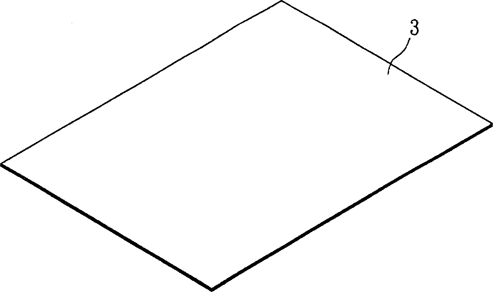
technical field [0001] The invention relates to a metal outer frame, in particular to a method for manufacturing the metal outer frame used for flat-panel displays. Background technique [0002] refer to figure 1 , shows a three-dimensional schematic view of the metal frame of the traditional backlight module. The metal frame 1 covers the backlight module 2 to fix the backlight module 2 and strengthen the frame structure strength of the light box (housing) 21 of the backlight module 2. [0003] refer to Figure 2a to Figure 2e ,show figure 1 The manufacturing method of the traditional metal frame 1. [0004] refer to Figure 2a , first provide a sheet material 3 as the raw material to be processed, the sheet material 3 can be a coiled material or a sheet-like material, Figure 2a Material shown in sheet form. The material of the plate 3 is metal, such as iron, stainless steel, aluminum, tinplate, mild steel or galvanized steel plate. [0005] refer to Figure 2b , an...

Claims


Application Information

Patent Timeline
IPC IPC(8): B21D5/00B21D22/02B21D28/00B23K26/21B23P23/04H05K5/04
Inventor 范植职叶启东梁永升
Owner CHI LIN TECH CO LTD
Learn More