
Communication control system, communication control method, and relay device

A communication control and relay device technology, applied in transmission systems, digital transmission systems, instruments, etc., can solve the problem of not wanting to establish a TCP connection between the client and the relay device, generate a relay device, and restrict the use of relay device resources And other issues

Inactive Publication Date: 2005-09-14
NTT DOCOMO INC
View PDF0 Cites 0 Cited by
  • Summary
  • Abstract
  • Description
  • Claims
  • Application Information

AI Technical Summary

Problems solved by technology

[0009] However, in the TCP connection method between the client and the server using the relay device according to the above-mentioned conventional procedure, the relay device receives the client's sending The TCP connection establishment request signal, so there is a problem that when the server cannot communicate, the resource load of the relay device and the unnecessary data volume billing on the client side occur.
[0010] That is, when the relay device unconditionally establishes a TCP connection with the client regardless of the state of the server to which the client connects, when the server does not exist, or the TCP connection between the relay device and the server cannot When established, the TCP connection between the relay device and the client remains in the relay device for a certain period of time, thus restricting the utilization of the resources of the relay device
[0011] In addition, in this case, when the communication network between the client and the relay device adopts the method of billing according to the amount of data, after the TCP connection between the client and the relay device is established, the data transmission starts and a certain amount of data, resulting in additional billing, therefore, in such cases, it is not desirable to establish a TCP connection between the client and the relay

Method used


Image

  • Communication control system, communication control method, and relay device
  • Communication control system, communication control method, and relay device
  • Communication control system, communication control method, and relay device

Examples


Embodiment Construction

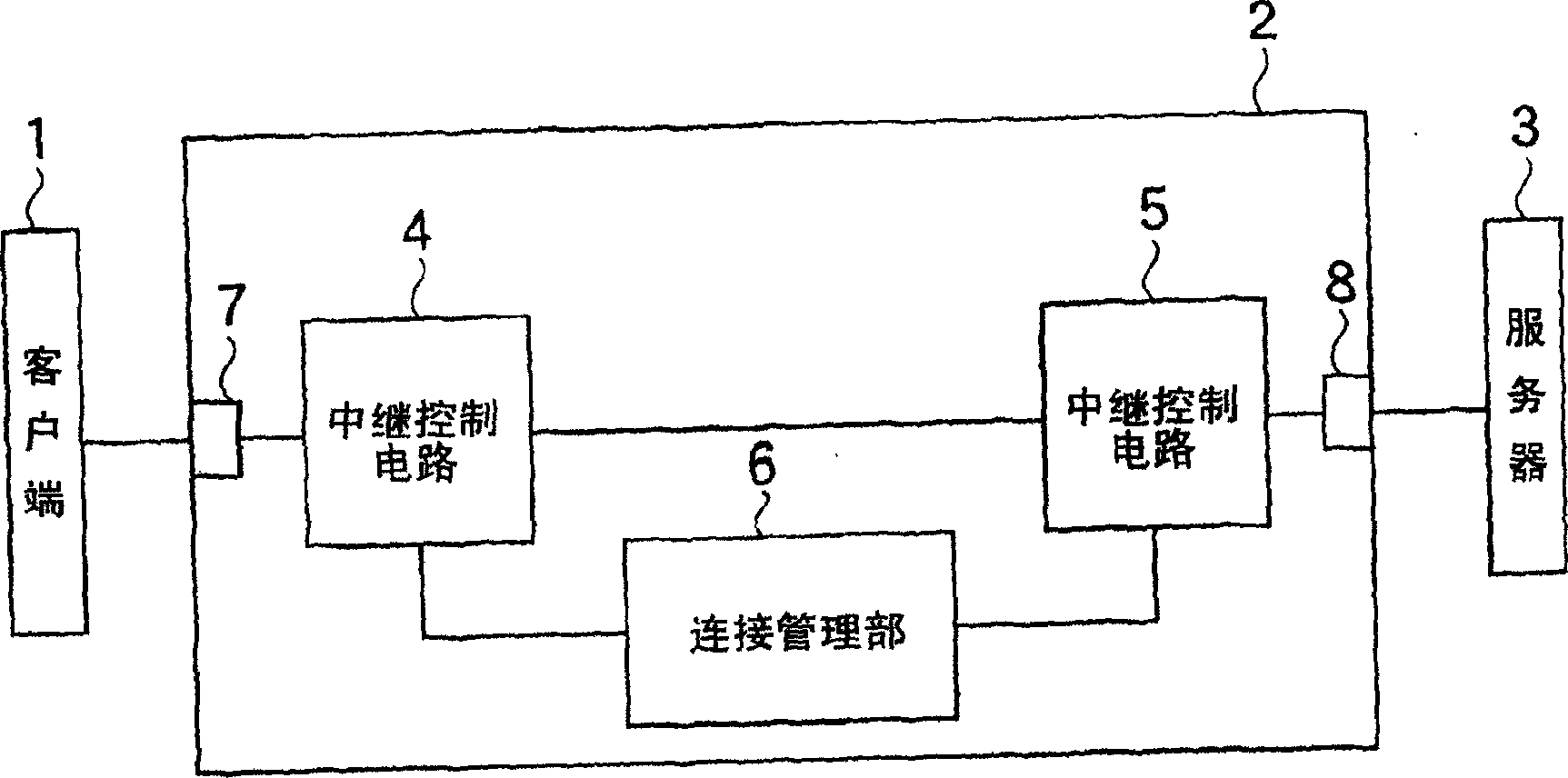
[0029] (Structure of the communication control system of one embodiment of the present invention)

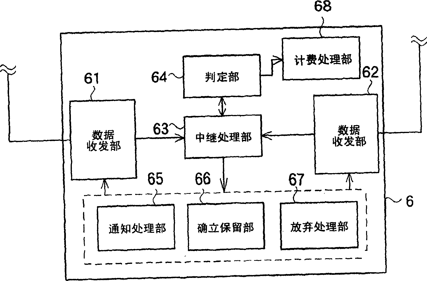
[0030] Refer to the following Figure 1A and Figure 1B A communication control system according to an embodiment of the present invention will be described.

[0031] like Figure 1A As shown, the communication control system of this embodiment has a client 1 , a server 3 and a relay device 2 . Here, the client 1 and the server 3 are connected through a communication network such as the Internet. In addition, the relay device 2 is arranged between the client 1 and the server 3 .

[0032] The relay device 2 has a client-side connection terminal 7 , a server-side connection terminal 8 , relay control circuits 4 and 5 , and a connection management unit 6 .

[0033] The connection terminal 7 on the client side is connected to the client 1 , and the connection terminal 8 on the server side is connected to the server 3 . The relay control circuits 4 and 5 are respectively connec...


PUM


Abstract

An object of the present invention is to reduce a load on the resource of a relay device (2) and to reduce the data-amount charging on a client, when communications are performed between a client (1) and a server (3). A communication control system according to the present invention includes: an establishment holder (66) configured to hold a response signal from being transmitted from the client-side connection terminal (7) to the client (1), when a client-side connection terminal (7) receives a connection request signal from the client (1); a decider (64) configured to detect a connection state of a server-side connection terminal (8) in response to the connection request signal, and to decide whether or not a connection can be established between the server-side connection terminal (8) and the server (1); and a relay processor (63) configured to transmit the response signal held by the establishment holder (66) and to establish communications between the client (1) and the server (3) so as to perform relay processing, depending on a result of decision made by the decider (64).

Description

technical field [0001] The present invention relates to a communication control system, a communication control method, and a relay device that control (digital) data communication between a server and a client through a communication network such as the Internet. Background technique [0002] At present, in a communication network such as the Internet, when a relay device that relays data between a client and a server receives a connection request signal (TCP connection establishment request signal) of a communication protocol such as TCP sent by the client, it does not Regardless of the state of the server to be connected, a TCP connection is unconditionally established between the client and the relay device, and a TCP connection establishment request is sent to the relay destination server to attempt to establish a TCP connection. [0003] Figure 5 and Figure 6 The method for establishing a TCP connection using the existing relay device 12 is shown. like Figure 5 an...

Claims


Application Information

Patent Timeline
Patent Type & Authority Applications(China)
IPC IPC(8): H04L12/70G06F13/00H04L29/06H04L29/08
CPCH04L69/16H04L67/24H04L67/14H04L67/54
Inventor 关口克己鹤卷宏治北口雅哉
Owner NTT DOCOMO INC
Learn More