Heating method for fuel oil in fuel oil storage tank

A heating method and fuel oil technology, applied in the arrangement combined with the fuel supply of internal combustion engines, liquid fuel engines, hull ventilation/heating/cooling, etc., can solve the problems of large effects and high construction costs

Active Publication Date: 2005-09-21
HOKUSHIN ENG
View PDF3 Cites 16 Cited by
  • Summary
  • Abstract
  • Description
  • Claims
  • Application Information

AI Technical Summary

Problems solved by technology

[0010] However, in the case of this device, the effect is great for high or d

Method used


Image

  • Heating method for fuel oil in fuel oil storage tank
  • Heating method for fuel oil in fuel oil storage tank
  • Heating method for fuel oil in fuel oil storage tank

Examples


Embodiment Construction

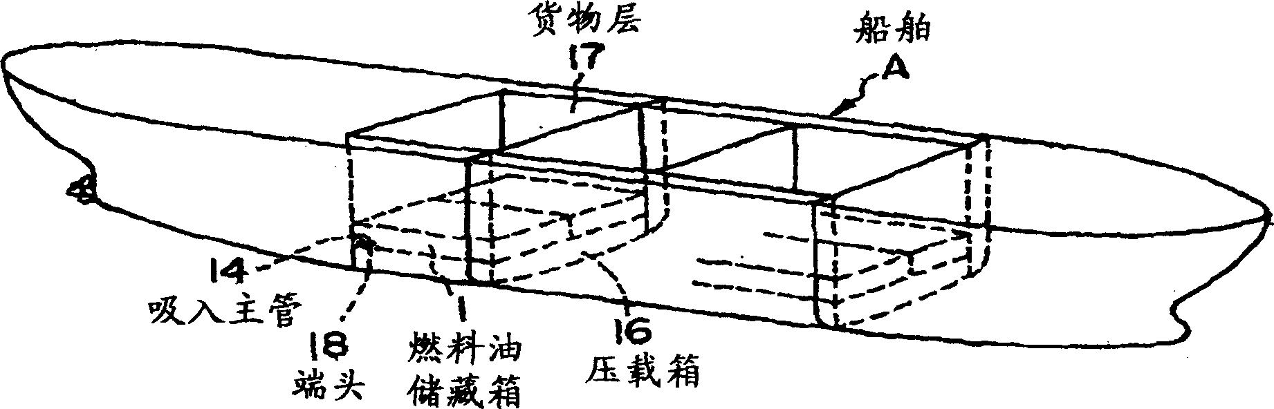
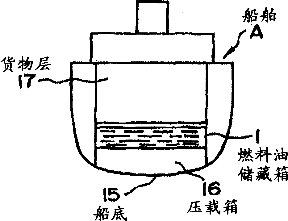
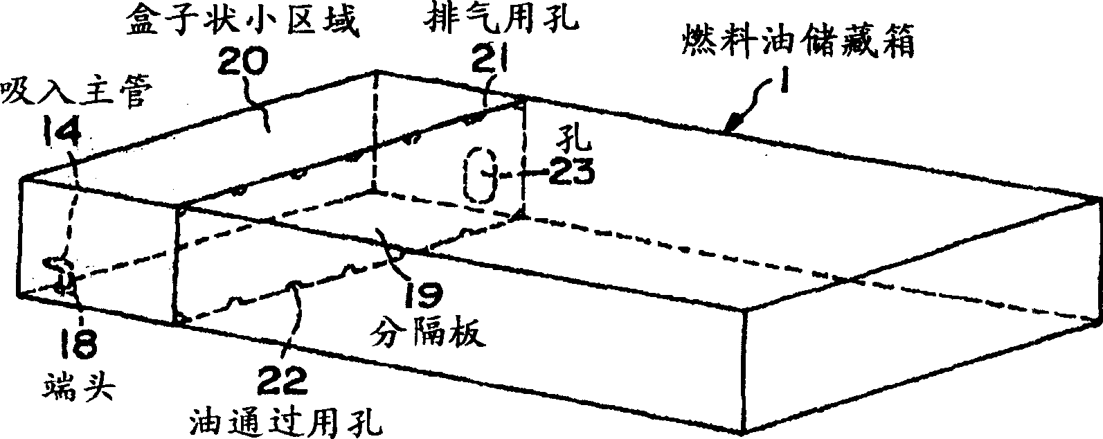
[0024] Hereinafter, the present invention will be described in detail with reference to the accompanying drawings. figure 1 It is an axonometric drawing showing the inside of a fuel oil storage tank of a ship. figure 2 yes figure 1 cross-sectional view. image 3 It is an axonometric view of a specific embodiment of the fuel oil storage tank involved in the present invention. Figure 4 , Figure 5 , Image 6 as well as Figure 7 It is a perspective view of another specific embodiment of the fuel oil storage tank according to the present invention. Figure 8 It is a flowchart showing the heating system of the fuel oil in the fuel oil storage tank.

[0025] Such as Figure 8 As shown, the heated fuel oil in the fuel oil storage tank 3 flows into the fuel oil in the fuel oil storage tank 1 through the suction main pipe 14 arranged in the fuel oil tank 1 for mixing, and the fuel in the fuel oil storage tank 1 is mixed. Oil warmed.

[0026] Such heating equipment as Figur...


PUM


Abstract

This invention provides a method for heating fuel oil in a fuel oil storage tank to warm the fuel oil in the tank to intended temperature by flowing down heated fuel oil to the storage tank and mixing the heated fuel oil in the tank, and in particular, to partially improve warming efficiency for the fuel oil in the tank. In this method for heating fuel oil in the fuel oil storage tank, heated fuel oil is flowed down to and mixed with the fuel oil in the fuel oil storage tank 1 via a main intake pipe 14, to warm the fuel oil in the fuel oil storage tank 1. A box shape small division 20 is formed in the storage tank 1 by surrounding the perimeter of a tip 18 of the main intake pipe 14 by a partition plate. By preventing diffusion and heat release of the heated fuel oil flowed in through the tip 18, warming efficiency for the fuel oil is partially improved.

Description

technical field [0001] The present invention relates to a method for heating fuel oil in a fuel oil storage tank of a ship, etc. Specifically, it relates to making the fuel oil heated in a clarification tank flow from a clarification tank or an auxiliary fuel tank into a storage tank for mixing, and the A heating method for heating fuel oil in a fuel tank to a desired temperature, in particular, relates to a heating method for fuel oil in a fuel oil storage tank that partially improves the heating efficiency of the fuel oil in the fuel tank. Background technique [0002] In a ship, etc., when fuel oil is supplied to the engine, the fuel oil is usually sent from the fuel oil storage tank through the delivery pipe to the fuel oil tank by the delivery pump, where the fuel oil is heated and then passed through the fuel oil auxiliary tank. (Small fuel oil tank) and fuel oil purifier etc. are supplied to the engine. At this time, the fuel oil in the fuel oil storage tank needs to...

Claims


Application Information

Patent Timeline
IPC IPC(8): B63B11/04B63H21/38F02N19/04
CPCB60K15/077B63B11/04B63B17/0027B63H21/38B63J2/12F04D29/007F04D29/44Y10S417/00
Inventor 千千波孝泰
Owner HOKUSHIN ENG
Why Eureka
Try Eureka