Reflex-type screen assembly

一种反射式屏幕、方向反射的技术,应用在反射式屏幕领域,能够解决难以提供反射式屏幕反射性和散射性、制造方法难以增加屏幕尺寸、制造方法复杂等问题

Inactive Publication Date: 2005-09-21
ARISAWA MFG CO LTD
View PDF3 Cites 41 Cited by
  • Summary
  • Abstract
  • Description
  • Claims
  • Application Information

AI Technical Summary

Problems solved by technology

When the exposure method is to be used, it is difficult to increase the size of the screen due to the limitation of the manufacturing method
In addition, in order to obtain different viewing angle characteristics between the vertical direction and the horizontal direction, multiple exposures are required, which makes the fabrication method more complicated
[0007] In addition, when the transparent resin panel disclosed in Japanese Patent Laid-Open No. 11-44805 is used for a reflective screen, there is a problem that it is difficult to provide reflectivity and scattering required for a reflective screen in a zigzag cross section. sex

Method used


Image

  • Reflex-type screen assembly
  • Reflex-type screen assembly

Examples


Embodiment Construction

[0018] The present invention will be described below according to preferred implementations. The purpose of these preferred embodiments is not to limit the scope of the present invention, but to illustrate the present invention. All the features of the present invention described in the embodiments and combinations thereof are not necessarily essential to the present invention.

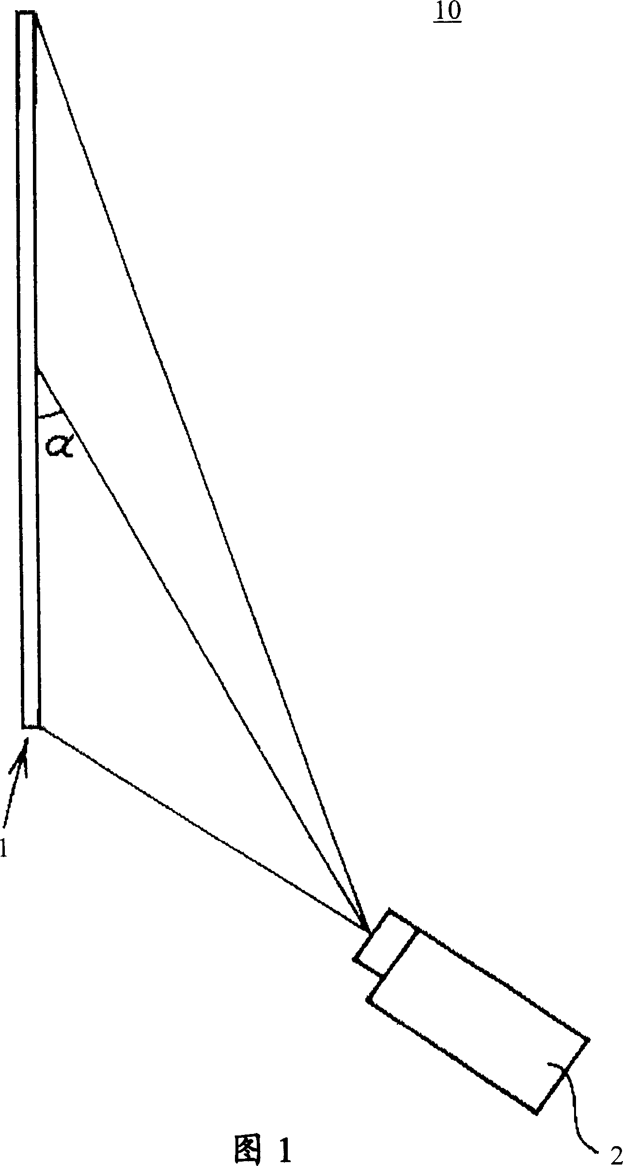
[0019] FIG. 1 shows an exemplary structure of a reflective screen device 10 according to an embodiment of the present invention. The reflective screen device 10 includes a reflective screen 1 and a projector 2 . For example, projector 2 is a short focal length projector. The projector 2 projects imaged light at an angle from the viewer's side of the reflective screen 1 . For example, imaging light is projected to the reflective screen 1 from the lower front. The set projector 2 is about 0.3 meters to 0.7 meters away from the reflective screen 1 . The reflective screen 1 reflects the imaged light f...


PUM


Abstract

A reflex-type screen includes a base which has saw-tooth appearance, and an optical absorption layer on one edge of each saw-tooth of the base. The base consists of white resin and includes a plurality of projector side inclined planes and non-projector side inclined planes, which are alternately provided to form the saw-tooth appearance. The projector side inclined planes are oriented so that the image light from the projector may be incident on them, while the non-projector side inclined planes are oriented so that the image light from the projector may not be incident on them. The optical absorption layer is formed on each of the non-projector side inclined planes of the base to absorb the light. The projector side inclined plane reflects the image light just in front of the observer of the reflex-type screen from the projector.

Description

[0001] This patent application claims priority to U.S. Provisional Application No. 60 / 552,720, filed March 15, 2004, and U.S. Nonprovisional Application No. 10 / 980,339, filed November 4, 2004, the entire contents of which applications are incorporated Here for reference. technical field [0002] The present invention relates to a reflective screen for displaying an image projected from a projector, and a reflective screen device equipped with the reflective screen. Background technique [0003] Traditionally, there has been a need to display an on-screen image to a viewer located directly in front of the screen by projecting the image at an angle at a short distance onto a reflective screen. When a commonly used white matte reflective screen is used for this purpose, it cannot be projected to a mirror located directly in front of the reflective screen because most of the imaged light projected from the short focal length projector is reflected to a place where there is no vi...

Claims


Application Information

Patent Timeline
Patent Type & Authority Applications(China)
IPC IPC(8): G03B21/56G03B21/60
CPCG03B21/60G03B21/56
Inventor 丹羽政敏丸田一小柳贵博
Owner ARISAWA MFG CO LTD
Why Eureka
Try Eureka