
Operation vehicle

A technology for working vehicles and continuously variable speed change devices, which is applied in the fields of agriculture, vehicle parts, agricultural machinery and implements to achieve good detection accuracy, maintain detection accuracy, and maintain speed change accuracy.

Inactive Publication Date: 2005-10-05
KUBOTA LTD
View PDF3 Cites 6 Cited by
  • Summary
  • Abstract
  • Description
  • Claims
  • Application Information

AI Technical Summary

Problems solved by technology

[0007] Also, in JP-A-2002-362403, there is also the same problem of the above-mentioned time lag caused by the hysteresis of the control system.

Method used


Image

  • Operation vehicle
  • Operation vehicle
  • Operation vehicle

Examples


Embodiment Construction

[0049] Hereinafter, a suitable embodiment of the work vehicle of the present invention will be described with reference to the drawings using a combine as an example of one type of agricultural work machine.

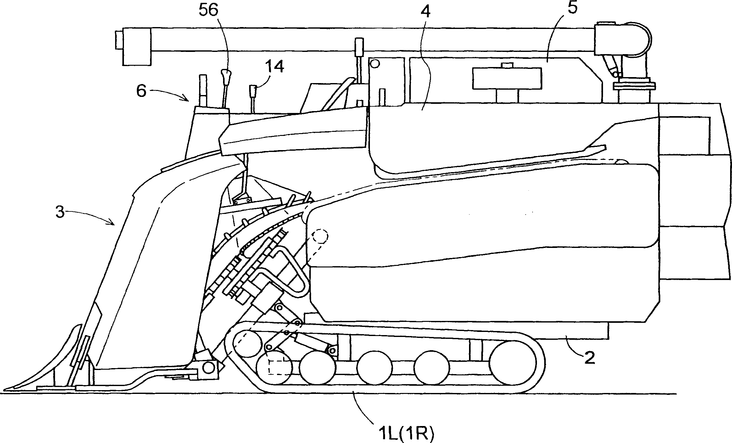
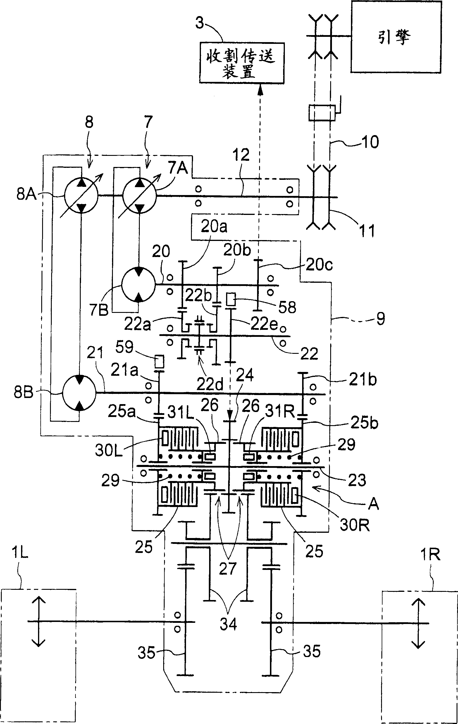
[0050] figure 1 Shows the overall side view of the combine harvester. The combine harvester is constituted by a reaping conveyer 3 that reaps planted grain stalks and conveys them rearwardly connected to the front portion of a traveling body 2 that is driven by a pair of left and right crawler-type traveling devices 1R and 1L. On this traveling body 2, the threshing device 4 which receives the harvested grain stalk from the reaping conveyance device 3, and performs threshing and sorting process, and the grain container 5 which stores the grain from the threshing device 4 are mounted. Riding and driving portion 6 is formed in front of grain container 5 .

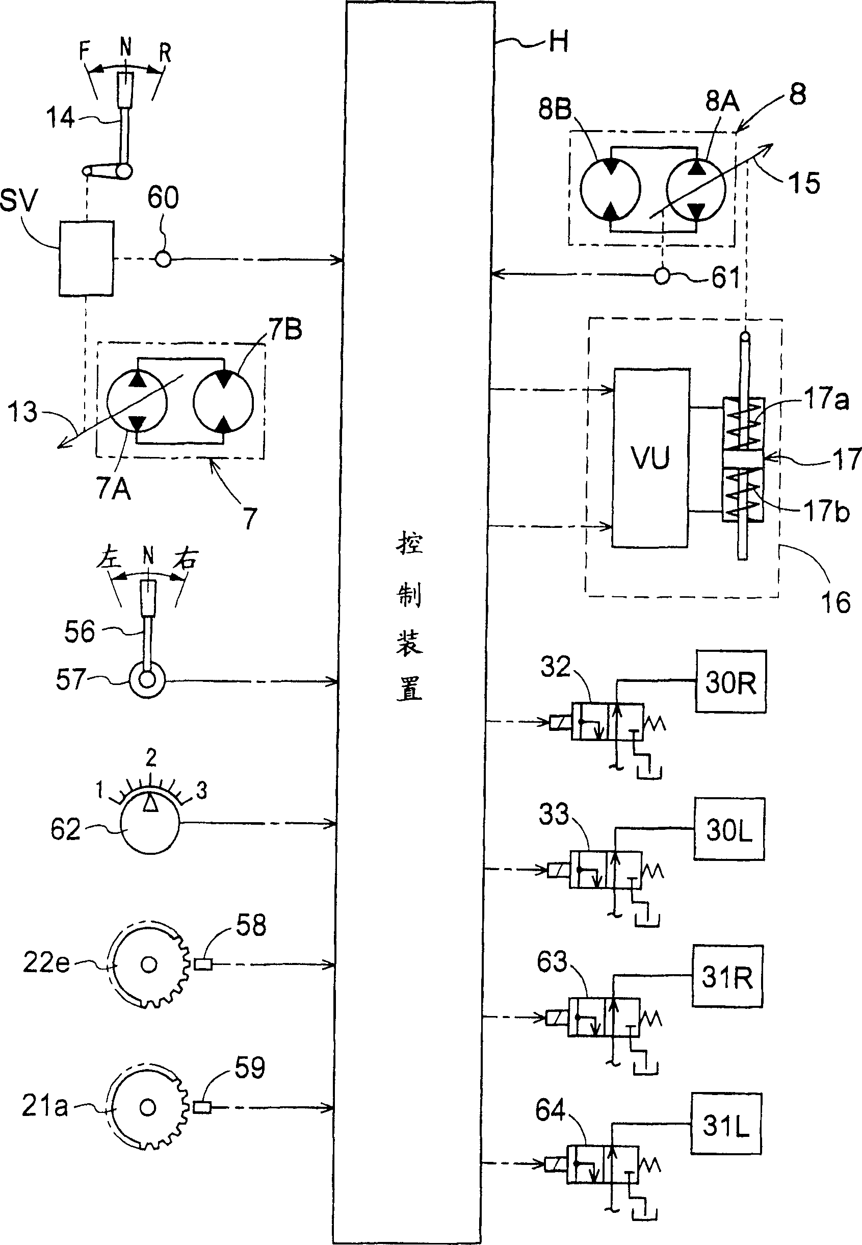
[0051] Such as figure 2 and image 3 As shown, the drive train of the combine harvester has: a straight continuo...


PUM


Abstract

The invention provides an operation vehicle comprising left and right running gears (1R, 1L), an engine (3), a continuously variable transmission device (7) for straight running and a continuously variable transmission device (8) for turning, a speed command means (14), a turning command means (56), wherein the operation vehicle is also provided with a speed detection means and control unit (H). When the command of the turning command means (56) is switched from turning to straight running, the continuously variable transmission device for straight running performs the shift operation, based on the command speed of the speed command means (14) and the continuously variable transmission device for turning performs the shift operation using control unit (H), so that the two continuously variable transmission device have the same speed, and the shift operation speed of the transmission device for turning at that time is made greater than the shift operation speed of the transmission device for straight running on the basis of a speed command means.

Description

technical field [0001] The present invention relates to work vehicles. More specifically, it relates to a technology for improving the straight running and turning operability of agricultural working machines including harvesting working machines (combines and the like). technical background [0002] The prior art of this type of working vehicle, for example, has been disclosed on Japanese Patent No. 3174515 (or with reference to the publications corresponding to it: JP-A-10-157650, KR-A-1998-63749 or CN-A- 1191816). In this existing structure, there are a speed command mechanism, a turning command mechanism, a connecting rod connecting the two command mechanisms, a straight-going continuously variable transmission device and a turning continuously variable transmission device with a mechanically operated link connecting mechanism. When the turning command mechanism issues a straight-going command, the straight-going continuously variable transmission device shifts to the ...

Claims


Application Information

Patent Timeline
IPC IPC(8): A01B59/00B62D11/10
CPCA01B69/007
Inventor 山中之史上田吉弘林繁树加藤裕治
Owner KUBOTA LTD
Learn More