Yarn joining device and handy splicer

A technology of jointing device and splicer, which is applied in the direction of jointing device, transportation and packaging, textiles and papermaking, etc., to achieve the effect of easy untwisting

Inactive Publication Date: 2005-10-05
MURATA MASCH LTD
View PDF1 Cites 15 Cited by
  • Summary
  • Abstract
  • Description
  • Claims
  • Application Information

AI Technical Summary

Problems solved by technology

However, even in the case of the jointing method and jointing device described in this patent document 1, it has not yet become th...

Method used


Image

  • Yarn joining device and handy splicer
  • Yarn joining device and handy splicer
  • Yarn joining device and handy splicer

Examples


Embodiment Construction

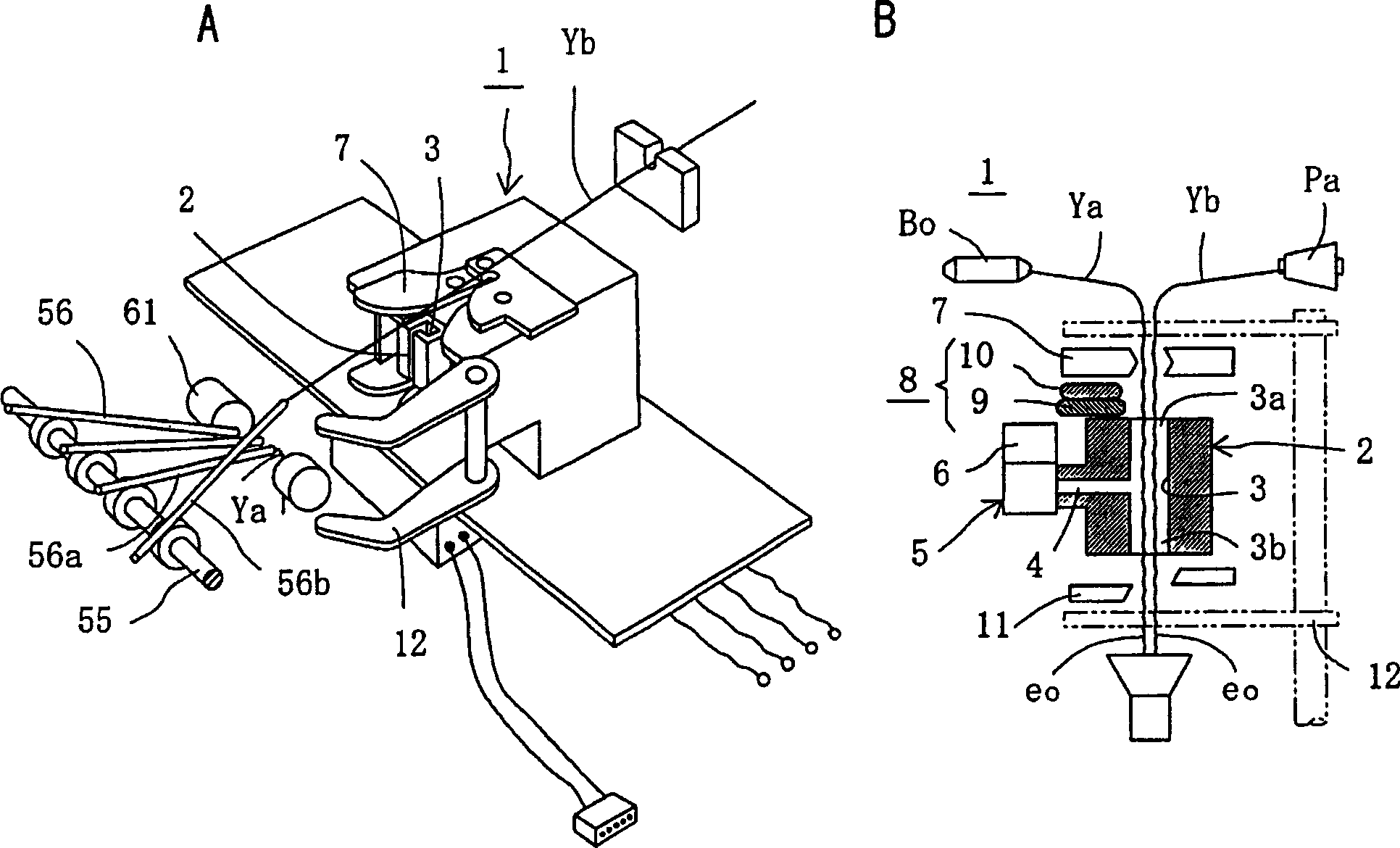
[0026] Next, referring to the specific embodiments shown in the accompanying drawings, the joint device of the present invention will be described in detail. figure 1 is a schematic diagram of an example of the splicing device of the present invention, figure 1 A is a schematic perspective view showing a structural example of applying the device to a piecing portion of a winder, figure 1 B is a side sectional view showing the main part of the joint device in section.

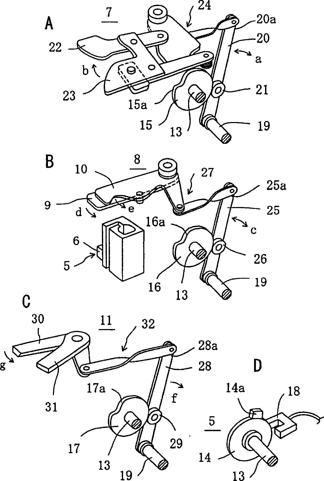
[0027] on the other hand, figure 2 In the splicing device of the present invention, each mechanism for operating each mechanism is disassembled and shown separately, figure 2 A is a schematic perspective view showing the operating mechanism of the clamping mechanism for gripping two yarns in a state where the yarn ends are aligned in the same direction, figure 2 B is a schematic perspective view showing the operating mechanism of the seam length adjusting mechanism for closing one side of the yarn receivin...


PUM


Abstract

The present invention provides a yarn joining device for joining two yarns (Ya,Yb) with the tail ends (eo) thereof aligned in the same direction. The yarn joining device reduces the size of the joint portion of the yarns even if the yarn joining is successively performed, and also adjusts the yarn joining length, and thereby forms the joint portion of yarns uniformly and reliably. In the yarn joining device for joining tail ends of two yarns with the tail ends aligned in the same direction, loosening and twining of the tail ends of the yarns is performed successively by a single air jet nozzle (2).

Description

technical field [0001] The present invention relates to a splicing device for splicing the yarn ends of two yarns, in particular to a splicer type splicing device in which the yarn ends of two spliced ​​yarns are aligned in the same direction. A splicing device and a portable splicer constructed so that the splicing device can be transported. Background technique [0002] As known in the art, conventional jointing devices include a jointing device called a knotter and a jointing device called a splicer. The former forms a knot and joints; the latter combines two yarns in advance. The yarn end part is untwisted, and the yarn end part is overlapped in the opposite direction in the joint hole, and the compressed fluid (compressed air, etc.) The end parts rotate and vibrate to intertwine (环み合ゎせ) and joints. [0003] Among the above-mentioned piecing devices, in the piecing method performed by a piecing device called a knotter, the knot portion protrudes along the entire circum...

Claims


Application Information

Patent Timeline
IPC IPC(8): B65H69/06D01H15/00
CPCB65H69/061B65H2402/414B65H2701/31
Inventor 美马博志畠山泰典铁见太郎
Owner MURATA MASCH LTD
Why Eureka
Try Eureka