
Polarization controller and use thereof

A technology of polarization controller and polarization state, which is applied in the direction of instruments, electromagnetic wave transmission systems, optics, etc., can solve the problems of inability to achieve precise control, affect the speed of control, and unstable performance, and achieve simple structure, avoid mechanical rotation, low cost effect

Inactive Publication Date: 2005-10-05
TSINGHUA UNIV
View PDF0 Cites 4 Cited by
  • Summary
  • Abstract
  • Description
  • Claims
  • Application Information

AI Technical Summary

Problems solved by technology

Among them, the optical fiber extrusion / winding type polarization controller mainly uses piezoelectric ceramics and other devices to apply external forces in different directions to the optical fiber, thereby generating a stress birefringence effect to change the polarization state. The advantages are that the structure is relatively simple and the cost is relatively low. However, due to factors such as physical fatigue, its performance is unstable and precise control cannot be achieved; the wave plate rotation polarization controller is cascaded through more than three half-wave plates and quarter-wave plates, and is manually or electronically controlled Rotate the main axis direction of the wave plate to introduce birefringence in different directions, so as to achieve the purpose of polarization control. This method is more accurate than the fiber extrusion / winding type, but it affects the control speed due to the mechanical rotation of the wave plate. ; The polarization controller of liquid crystal / electro-optic modulation type uses liquid crystal or LiNO 3 The electro-optical effect of crystals introduces birefringence in different directions to control the polarization state. This method has high precision and fast speed, but the structure is complex and the cost is high.

Method used


Image

  • Polarization controller and use thereof
  • Polarization controller and use thereof
  • Polarization controller and use thereof

Examples


Embodiment Construction

[0012] 1. The principle analysis of Faraday rotator realized by magneto-optic crystal.

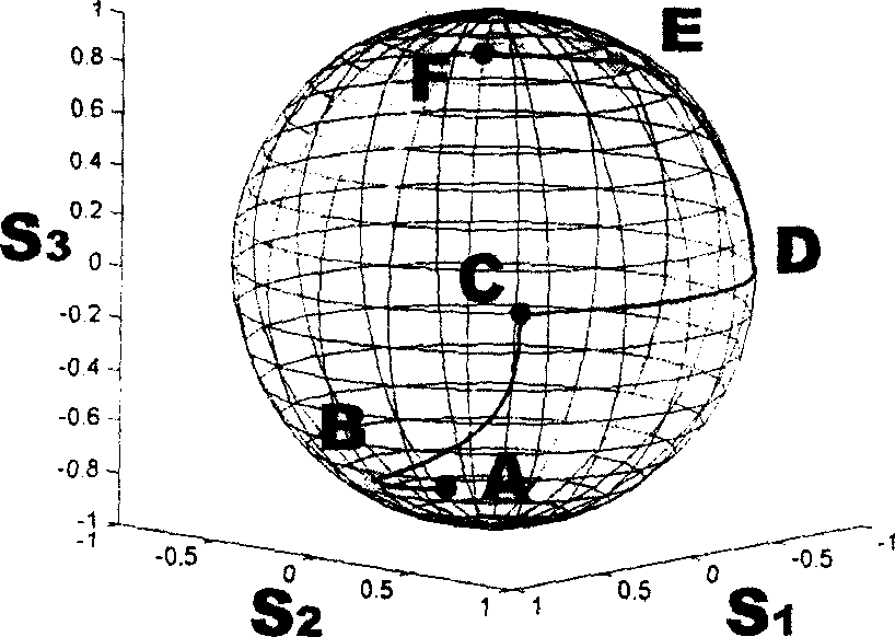
[0013] The magneto-optic effect, also known as the Faraday effect, refers to the phenomenon of circular birefringence in the material when a magnetic field is applied to the magneto-optic material, that is, right-handed polarized light and left-handed polarized light experience different refractive indices in the medium. The magneto-optic effect makes the polarization state of light propagating in the magneto-optic medium along the S of the Stokes space 3 The axis rotates, and its rotation angle is related to the strength of the magneto-optic effect, which can be controlled by changing the strength of the magnetic field applied to the magneto-optic material. This rotation effect on the polarization state can be represented by the following Jones matrix J and Stokes matrix S:

[0014] J = cos α ...


PUM


Abstract

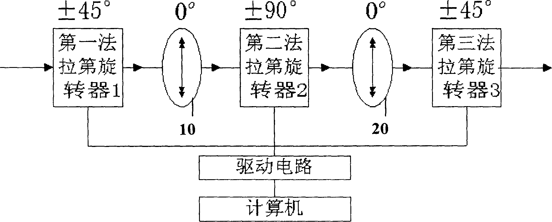
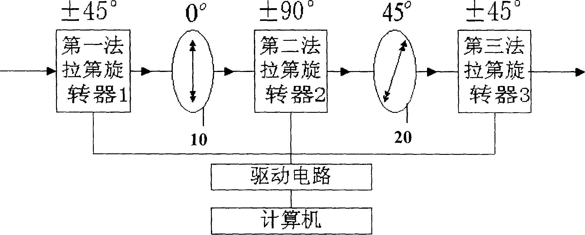
The invention is a polarization controller and its application. For realizing the polarization control and the random disturbing function of polarizing state, the invention discloses a polarization controller, including an optical part and an electric control part composed of driving circuits, where the optical part is formed cascadedly and alternatively of three magnetooptical crystal-made Faraday rotators and two 1 / 4 wave plates along the light path, and the two wave plates are fixed and the three Faraday rotators are controlled by the electric control part at the rotating angles of plus or minus 45 degrees, plus or minus 90 degrees and plus or minus 45 degrees, respectively, so as to realize the conversion of arbitrary determined input polarizing state to arbitrary determined output polarizing state. The structure is simple, the control is accurate, the cost is low and it is easy for system integration.

Description

technical field [0001] The invention belongs to the field of optical fiber communication. Background technique [0002] In the optical fiber communication system, the polarization state of the optical signal often has obvious fluctuations in the process of propagating along the optical fiber and various optical devices, and the receiving end requires an optical signal with stable polarization characteristics, especially the polarization multiplexing system requires demultiplexing. To accurately identify the polarization state at the receiving end, it is necessary to accurately control the polarization state of the optical signal at the receiving end. In addition, with the continuous improvement of the single channel rate of the optical fiber communication system and the wide application of the dense wavelength division multiplexing system, the polarization mode dispersion effect is considered to be the ultimate obstacle to the development of the optical communication system ...

Claims


Application Information

Patent Timeline
Patent Type & Authority Applications(China)
IPC IPC(8): G02F1/09G02F1/095H04B10/25
Inventor 杨昌喜张阳李世光
Owner TSINGHUA UNIV
Learn More