Frame structure for back-light module

A frame structure and backlight module technology, applied in optics, nonlinear optics, instruments, etc., can solve problems such as restrictions, discounted fixed effects, and large intervals

Active Publication Date: 2005-10-05
AU OPTRONICS CORP
View PDF1 Cites 9 Cited by
  • Summary
  • Abstract
  • Description
  • Claims
  • Application Information

AI Technical Summary

Problems solved by technology

And because the mouth-shaped fastening element a and the bump fastening element b are required to be as same as the assembly convenience image 3 There will also be a certain gap c as shown, which makes the fixed effect discounted
[0006] Therefore, no matter whether it is a straight hook structure or a mouth-shaped hook structure, the restriction direction can only be limited in the up and down direction, while the left and right directions must be kept large because of the convenience of combination, so it cannot Make effective restrictions in the left and right directions
Therefore, the existing backlight module fixing frame structure does not provide an effective positioning function

Method used


Image

  • Frame structure for back-light module
  • Frame structure for back-light module
  • Frame structure for back-light module

Examples


Embodiment Construction

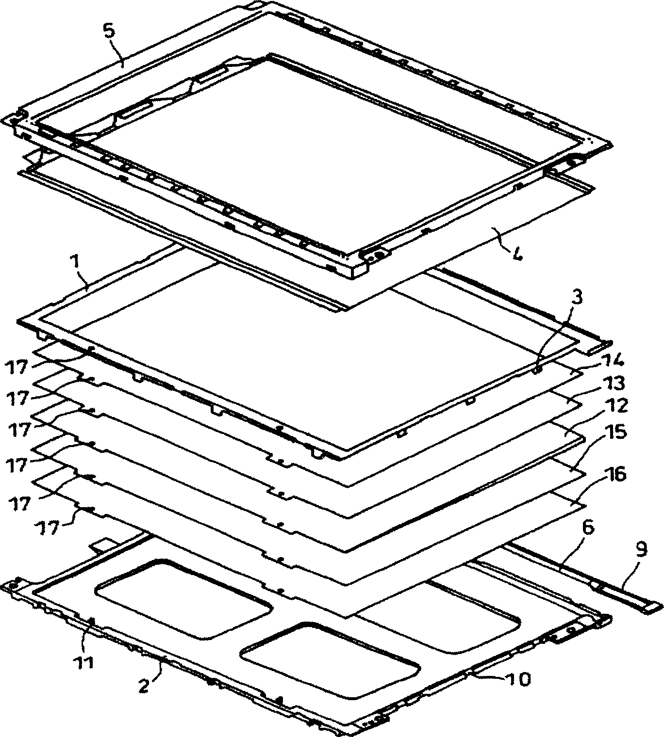
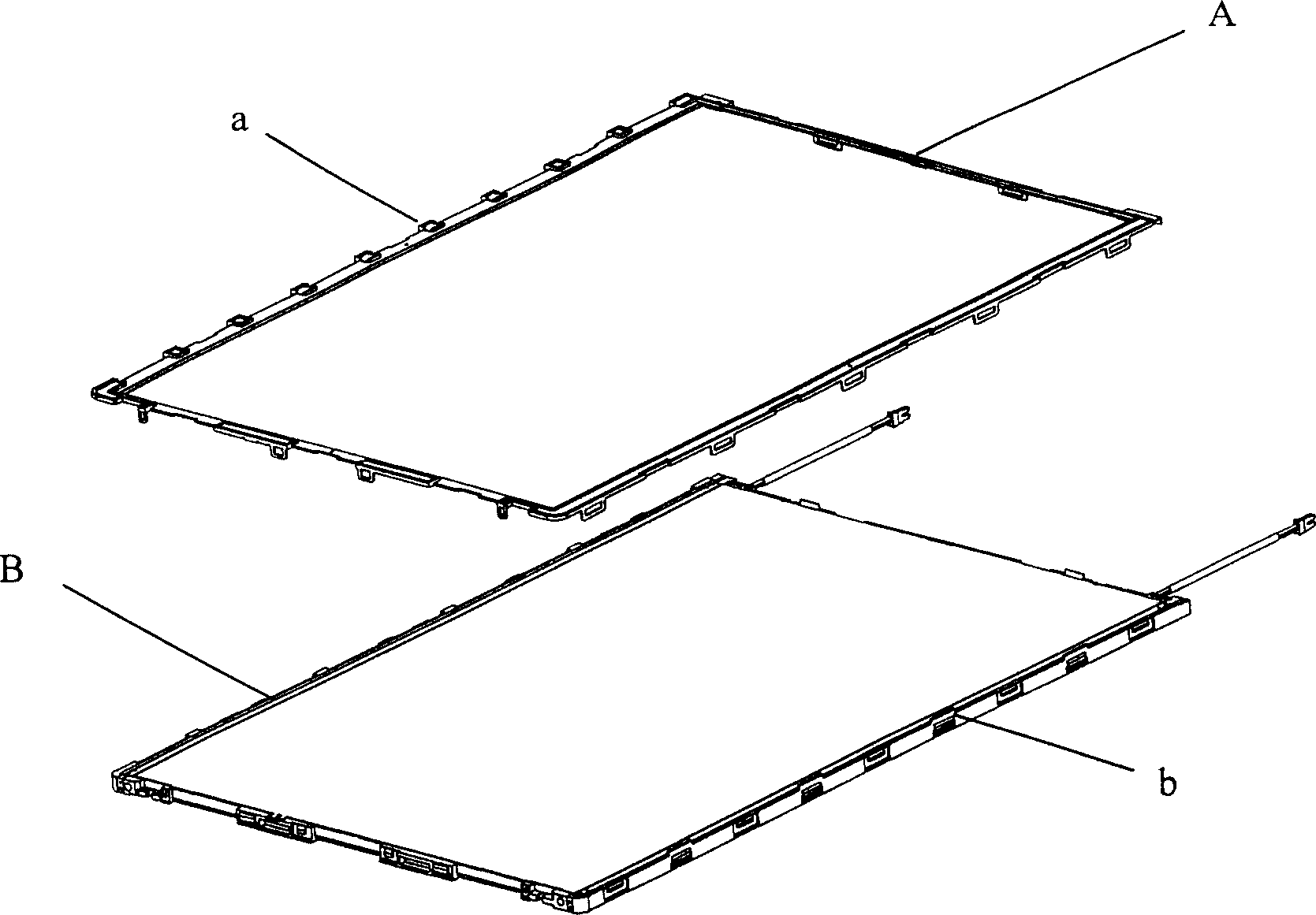
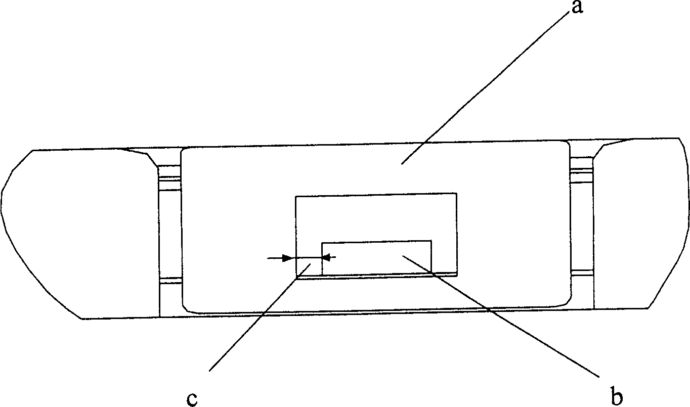
[0019] First, see Figure 4 . Figure 4 It is an exploded view showing the structure of the backlight module 20 utilizing the new frame structure of a preferred embodiment of the present invention. As shown in the figure, the backlight module is mainly composed of a plastic upper fixing frame 21, an upper diffusion plate 22, a light enhancement film 23, a lower diffusion plate 24, a light guide plate 25, a light source group and a metal or plastic lower fixing frame. The frame 26 is assembled sequentially from top to bottom; where the above-mentioned backlight module assembly is completely fixed by using the upper fixing frame and the lower fixing frame to achieve integration. The upper fixing frame has a fitting element that simultaneously restricts lateral movement and longitudinal movement, and the lower fixing frame has a corresponding fitting member that cooperates with the fitting element. For the specific structure of the fitting element and the corresponding fitting m...


PUM


Abstract

The invention is a frame structure for backlight module, used in a new frame structure of the backlight module, and composed mainly of top fixing frame and bottom fixing frame, and it can have good functions of fixing and locating the components of the backlight module, including linear light source, light source fixing base, light guiding plate, top diffusion plate, reflection plate, bottom diffusion plate, light intensifying film, and other components, by the combination of T-shaped fastening hook fixing components of the top fixing frame and groove components of the bottom fixing frame.

Description

technical field [0001] The invention relates to a frame structure for a backlight module, in particular to a frame structure suitable for fixing a backlight module of a liquid crystal display. Background technique [0002] Nowadays, liquid crystal displays are quite popular in current information or home appliances, and are widely favored by consumers due to their advantages of relatively low price and mature manufacturing technology. [0003] The display mode of the liquid crystal display adopts a passive mode, that is, its display must be illuminated by a light source of a backlight module. For this reason, a general liquid crystal display usually has a backlight module. However, liquid crystal displays are formed with extremely complicated and cumbersome structures, such as figure 1 As shown, a metal frame 5 is usually used, or a plastic upper frame 1 (Upper Frame) and a metal or plastic lower frame 2 (Lower Frame) are added to connect the liquid crystal panel 4 and the ...

Claims


Application Information

Patent Timeline
IPC IPC(8): G02F1/1335
Inventor 李思汉庄永彬吕理煌萧登昆
Owner AU OPTRONICS CORP
Why Eureka
Try Eureka