A high-precision paper office supplies punching device
A technology for office supplies and punching devices, applied in metal processing and other directions, can solve the problems that affect the user experience of the punching device, the lack of a fixed structure of the punching device, and the poor punching accuracy of the punching device, etc., so as to improve the user experience. , The structure is simple, the effect of improving work efficiency
- Summary
- Abstract
- Description
- Claims
- Application Information
AI Technical Summary
Problems solved by technology
Method used
Image
Examples
Embodiment 1
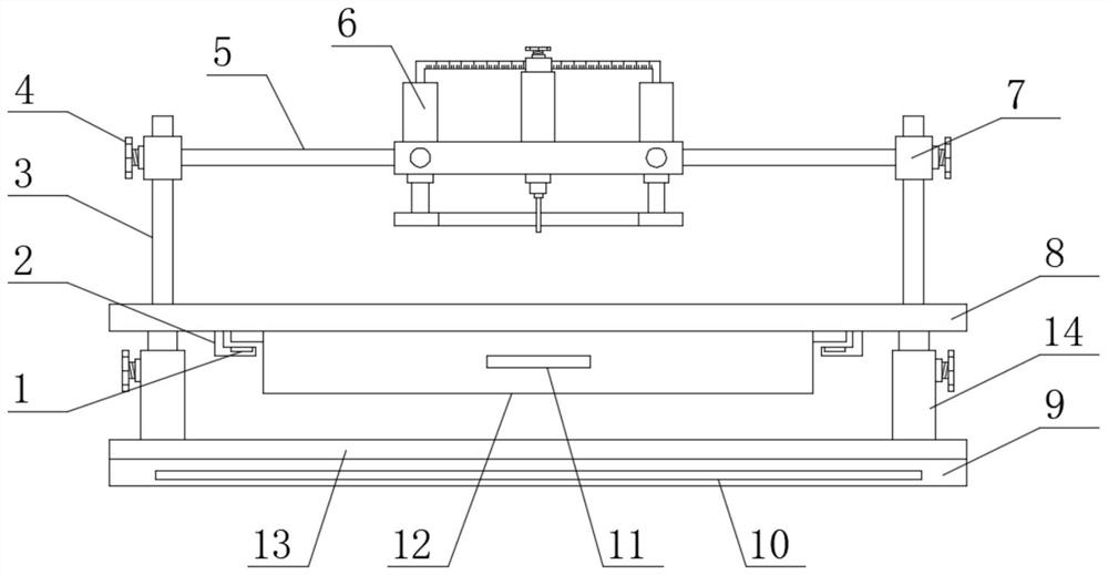
[0024] see Figure 1-Figure 4 , the present invention provides a technical solution: a high-precision paper-based office supplies punching device, including a second support plate 13, a first support plate 8 is arranged on the top of the second support plate 13, and a The two ends of the surface are welded with adjustable support rods 14 corresponding to the first support plate 8, the two ends of the upper surface of the first support plate 8 are provided with support side plates 3, and the top of the first support plate 8 is provided with a first limit Slide rail 5, the two ends of the first limit slide rail 5 are welded with the first limit sleeve 7 corresponding to the support side plate 3, one side of the first limit sleeve 7 is provided with the first adjusting bolt 4, One end of the first limit slide rail 5 is provided with a punching mechanism 6;
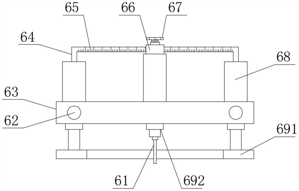
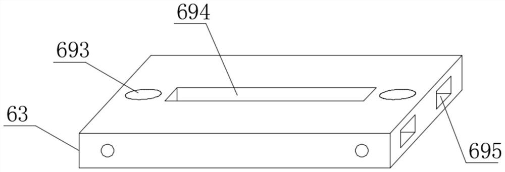
[0025] The punching mechanism 6 includes a third supporting plate 63, on which a third limiting through hole 695 correspon...
Embodiment 2
[0032] On the basis of Embodiment 1, in order to make the use of the punching device more convenient, in this embodiment, preferably, the front surface of the second limit slide rail 64 is provided with a scale 65, and the user can use the scale 65 to adjust the punching knife. 61 moving distance for precise adjustment;
[0033] In order to make the use of the second limiting sleeve 66 more reliable, in this embodiment, preferably, the top end of the second limiting sleeve 66 is provided with a third adjusting bolt 67 corresponding to the second limiting slide rail 64, When in use, the second limit sleeve 66 is fixed by the third adjusting bolt 67;
[0034] In order to make the fixing effect of the lower pressing plate 691 better, in this embodiment, preferably, the lower pressing plate 691 is a cuboid structure, and the inside of the lower pressing plate 691 is embedded with a heating resistance wire 697, and the heating resistance wire 697 is electrically connected to the po...
Embodiment 3
[0036]On the basis of embodiment 2, in order to make the anti-slip effect of the punching device better, in the present embodiment, preferably, the lower surface of the second support plate 13 is provided with an anti-slip backing plate 9, and the anti-slip backing plate 9 is a cuboid structure. The material of anti-slip backing plate 9 is rubber;
[0037] The anti-slip backing plate 9 and the second support plate 13 are bonded and connected by glue, and play an anti-skid effect through the anti-slip backing plate 9 during use, thereby preventing the punching device from sliding during use, so that the use of the punching device is more reliable;
[0038] In order to make the function of the anti-slip backing plate 9 more abundant, in the present embodiment, preferably, the inside of the anti-slip backing plate 9 is embedded with a second position-limiting magnet 10, the second position-limiting magnet 10 is a cuboid structure, and the second position-limiting magnet 10 NdFeB ...
PUM
 Abstract
Description
Claims
Application Information
 - R&D
- Intellectual Property
- Life Sciences
- Materials
- Tech Scout
- Unparalleled Data Quality
- Higher Quality Content
- 60% Fewer Hallucinations
Browse by: Latest US Patents, China's latest patents, Technical Efficacy Thesaurus, Application Domain, Technology Topic, Popular Technical Reports.
© 2025 PatSnap. All rights reserved.Legal|Privacy policy|Modern Slavery Act Transparency Statement|Sitemap|About US| Contact US: help@patsnap.com


