Laminoplasty devices and methods

A technology of laminoplasty and lamina, which is applied in the field of laminoplasty devices and laminoplasty bone plates, which can solve the problems of prolonging fusion time, inability to transplant bone fixation, time-consuming insertion, etc., and increase the cross-sectional area Effect

Inactive Publication Date: 2005-10-05
WARSAW ORTHOPEDIC INC
View PDF0 Cites 16 Cited by
  • Summary
  • Abstract
  • Description
  • Claims
  • Application Information

AI Technical Summary

Problems solved by technology

However, such sutures are technically difficult to suture, time-consuming to insert, and usually cannot firmly fix the grafted bone on the severed lamina
Consequently, subsequent movement between the grafted bone and one of the two severed lamina may deleteriously disrupt and / or prolong the fusion between them.

Method used


Image

  • Laminoplasty devices and methods
  • Laminoplasty devices and methods
  • Laminoplasty devices and methods

Examples


other Embodiment approach

[0100] In other embodiments, the flange on at least one distal end of the bone plate 2500 may be replaced by a lamina-engaging dimple or annulus that completely or substantially surrounds one end of the split lamina. Such dimples may advantageously reduce, constrain and / or prevent radial movement of the distal ends of the separated lamina segments up to 360 degrees along the lamina axis, thereby promoting fusion of the spinal canal and protecting it. Such dimples can be bent onto the distal ends of the separated lamina to securely engage them. In addition, such dimples may be lined and / or form one or more bone engaging means, such as dens, racks, sutures and / or sockets, for engagement with the lamina portion. Such a pocket may contain one or more fixation holes into which fasteners may be inserted to engage the pocket with the underlying lamina portion. Additionally, such dimples may contain surface and / or osteobioinductive substances that grow within the bone.

[0101] Fi...


PUM


Abstract

Laminoplasty plates are engageable to at least one portion of a divided lamina to maintain a desired spacing relative to the spinal canal. The laminoplasty plates include a spacer portion having a first end and a second end that spans a gap formed by at least one of a divided lamina portion. The laminoplasty plates can include a lamina engagement portion at one end for engagement with the divided lamina portion.

Description

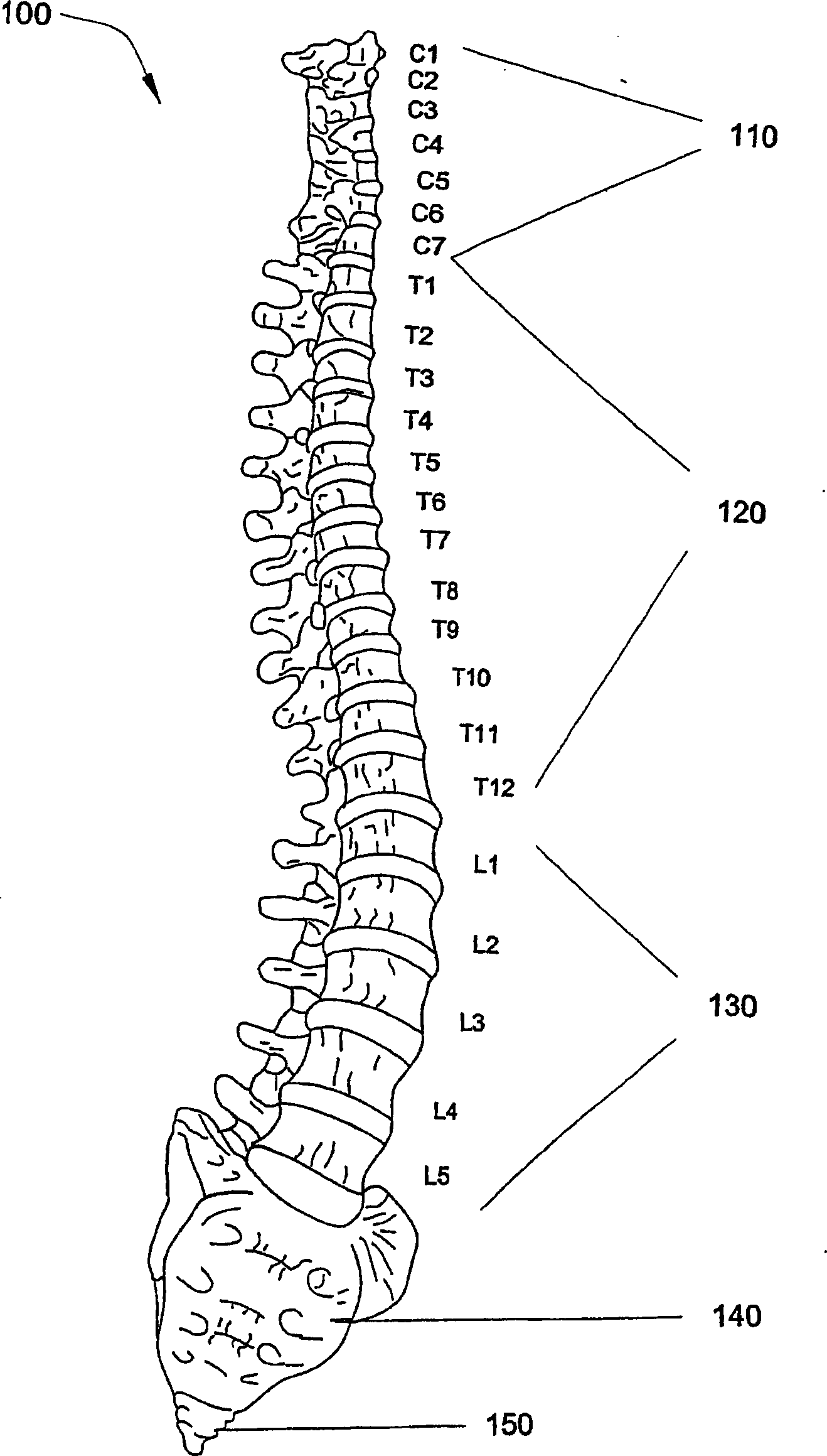
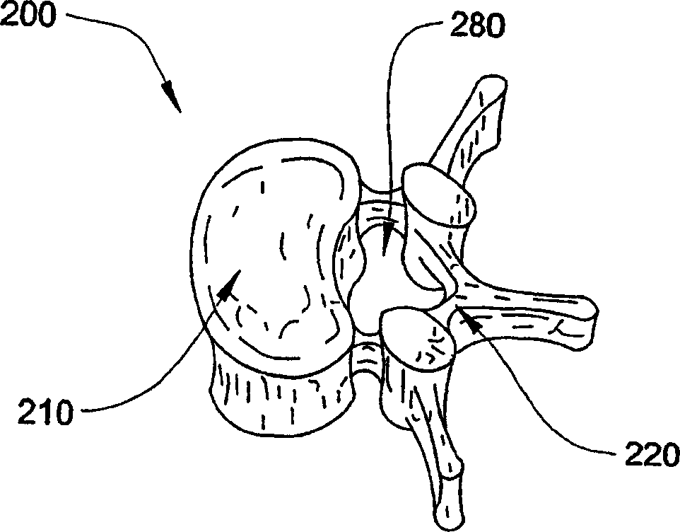
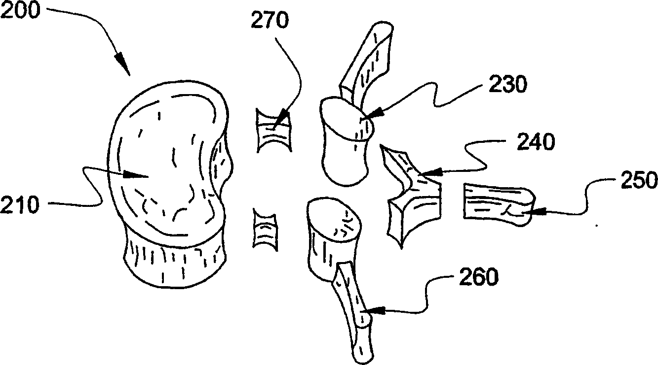
[0001] This application claims the benefit of Provisional Application Serial No. 60 / 384,573, filed May 30, 2002, which is hereby incorporated by reference in its entirety. technical background [0002] The present invention relates to the field of laminoplasty, and more particularly to devices and methods for laminoplasty. [0003] Every year many people suffer from traumatic neck, back and / or spinal injuries (see Figure 1 for a typical perspective view of a human spine 100, including the cervical 110, thoracic 120, lumbar 130, sacral 140 and coccygeal 150 regions). These injuries include cervical fractures, fracture-dislocations with retroverted discs, and other serious injuries. And every year many people undergo surgery for degenerative diseases, especially degenerative spinal stenosis. In spinal stenosis, narrowing of the spinal canal that houses and protects the spinal cord and nerve roots causes compression of the spinal cord and nerves. The goals of the surgery includ...

Claims


Application Information

Patent Timeline
Patent Type & Authority Applications(China)
IPC IPC(8): A61F2/44A61B17/70
CPCA61B17/7071A61B17/70A61B17/7059A61B2017/564
Inventor G·C·马利克W·B·诺尔R·W·维克利J·G·海勒J·C·王
Owner WARSAW ORTHOPEDIC INC
Why Eureka
Try Eureka