Brightness control system

A brightness and controller technology, applied in the direction of instruments, optics, static indicators, etc., can solve the problems of not being able to fully provide closed-loop feedback information, not being able to generate brightness output, not being able to generate brightness, etc.

Inactive Publication Date: 2005-10-12
O2 MICRO INC
View PDF0 Cites 20 Cited by
  • Summary
  • Abstract
  • Description
  • Claims
  • Application Information

AI Technical Summary

Problems solved by technology

Such an implementation of an ambient sensor control system for LCDs in automobiles does not produce sufficient brightness as required, or does not produce brightness output, at low temperatures
Therefore, the control system does not adequately provide closed-loop feedback information to more precisely control panel brightness

Method used


Image

  • Brightness control system
  • Brightness control system
  • Brightness control system

Examples


Embodiment Construction

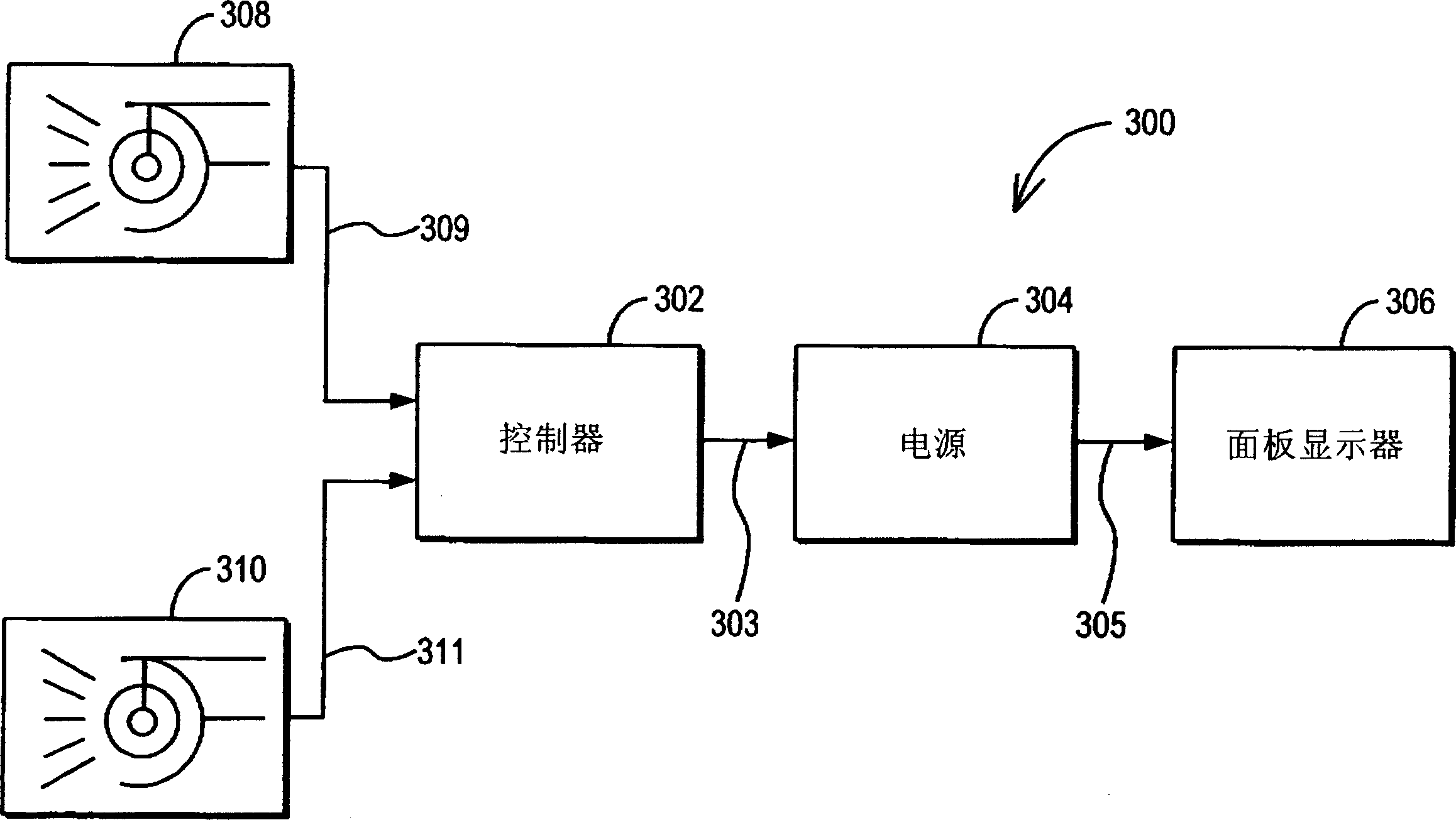
[0023] FIG. 3 depicts a system embodiment of a typical brightness control system 300 of the present invention. System 300 may include a power control circuit 302 (hereinafter "controller 302"), a power supply 304, a panel display 306, an ambient brightness sensor 308 and a panel brightness sensor 310. Power controller 302 may include a conventional and / or custom inverter control circuit that may generate at least one power control signal 303 . The power supply circuit 304 can use the power supply control signal 303 to output it as the target power of the power supply 304 . Therefore, the power control signal 303 can be used to control the operation of the power circuit 304 . Power circuit 304 may include a conventional and / or custom DC / AC inverter circuit. For example: well-known DC / AC inverter circuits can include full bridge, half bridge, push-pull, and / or ribbon (Royer) inverter topologies (and variations thereof), and the present invention can use any of them . Alterna...


PUM


Abstract

In one embodiment, the present disclosure provides a method to control the brightness of a display. One exemplary method includes generating a signal indicative of a display brightness level, and controlling the brightness of the display, based at least in part on the signal indicative of a display brightness level.

Description

technical field [0001] The present invention relates to a brightness control system. The present invention is generally applied to brightness control of LCD panel displays, plasma displays, field emission displays or light emitting diode displays and the like. These devices may be associated with portable computers, portable DVD players, portable electronic devices, and / or stand-alone panel monitors, and / or television displays. Background technique [0002] FIG. 1 depicts a conventional computer system 100 having a conventional LCD panel display 10 . A backlight inverter 20 for driving one or more cold cathode fluorescent lamps (CCFL) 22 and / or 24 includes a transformer 26 and a controller 28, as is well known in the art. A conventional computer system provides an LCD panel brightness value based on a command signal from the user, such as from a keyboard entry or a potentiometer within the computer. Once the brightness value is manually set, the brightness value of the LC...

Claims


Application Information

Patent Timeline
Patent Type & Authority Applications(China)
IPC IPC(8): G02B26/08G02F1/133G09G3/20G09G3/22G09G3/28G09G3/32G09G3/36G09G5/00G09G5/10
CPCG09G3/20G09G3/3406G09G2320/0626G09G2320/0633G09G2360/144G02F1/133
Inventor 林永霖
Owner O2 MICRO INC
Why Eureka
Try Eureka