
Antenna for portable cellular telephone

A wireless machine, portable technology, applied in the field of portable wireless machine antenna, to achieve the effect of high precision and easy installation

Inactive Publication Date: 2005-10-12
PANASONIC CORP
View PDF1 Cites 2 Cited by
  • Summary
  • Abstract
  • Description
  • Claims
  • Application Information

AI Technical Summary

Problems solved by technology

[0010] However, in conventional antennas for portable radios, a structure is adopted in which power can be supplied to the first antenna element 1 and the second antenna element 2 from a single power supply point 4, and two different resonant frequencies for obtaining GSM, DCS, etc. are shared. The matching circuit 5 makes it difficult to adjust the resonant frequencies of the two widely separated ranges independently and efficiently

Method used


Image

  • Antenna for portable cellular telephone
  • Antenna for portable cellular telephone
  • Antenna for portable cellular telephone

Examples


Embodiment Construction

[0034] Below, refer to Figure 1 to Figure 8 Embodiments of the present invention will be described. It should be noted that, in the following description, for example, terms indicating relative positional relationships such as "left side", "upper surface", and "lower surface" are used. It should be understood that it is for the convenience of explanation, and shows the relative positions of the various components placed in the state of facing the drawings, and does not represent the absolute positions of these components.

[0035] (Example)

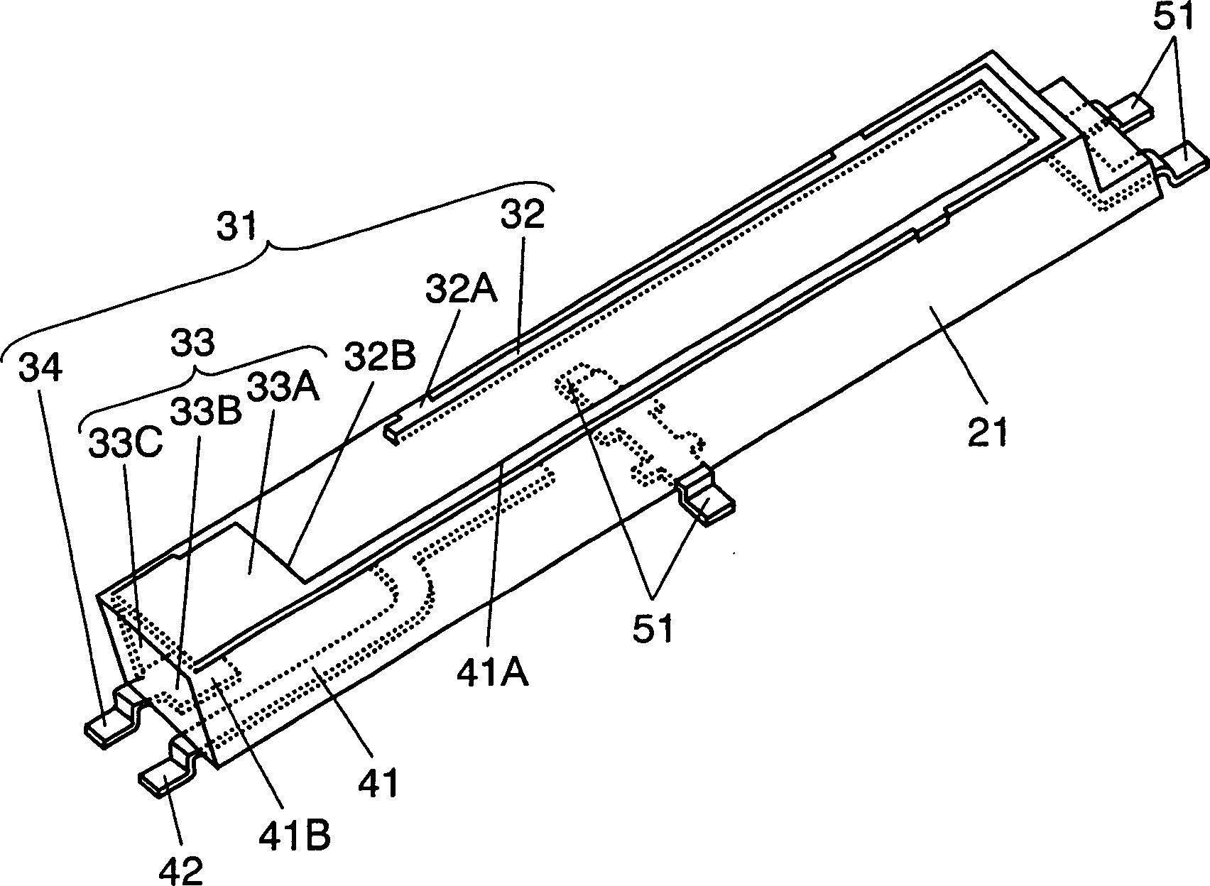
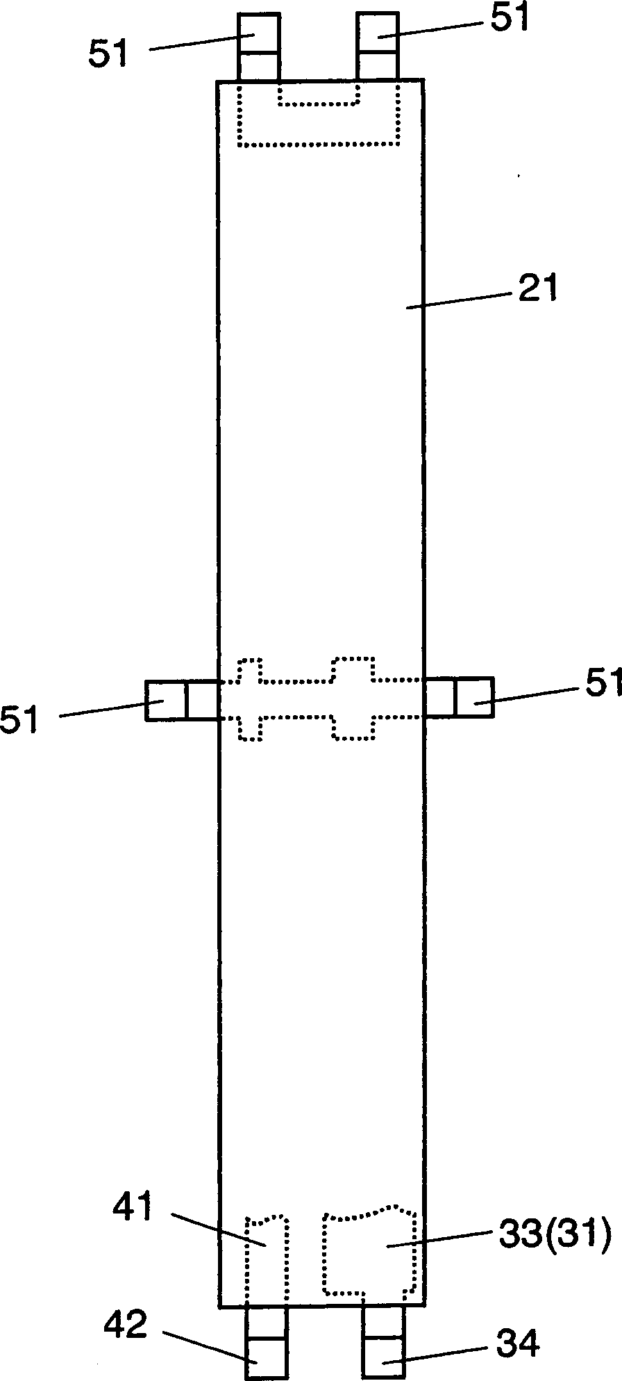
[0036] figure 1 is an external perspective view of an antenna for a portable wireless device according to an embodiment of the present invention, figure 2 is its top view.

[0037] exist figure 1 , figure 2 Among them, the base part 21 is formed in a size that can be accommodated inside a portable wireless device, and molded resin such as polyphthalimide (PPA) having heat resistance capable of surface mounting is used, and the ...


PUM


Abstract

An antenna for portable cellular telephone can adjust each of multiple antenna elements efficiently and independently to a predetermined resonance frequency. A first antenna element and second antenna element are mounted on and anchored to one common base. Terminals for feeding power to the first antenna element and the second antenna element are provided respectively. The terminals are coupled to matching circuits. This structure facilitates separate and efficient adjustment of resonance frequency of the first antenna element and the second antenna element.

Description

technical field [0001] The present invention relates to an antenna for a portable wireless device mounted on various portable wireless devices typified by mobile phones. Background technique [0002] In recent years, the miniaturization and weight reduction of various portable wireless devices have been progressing. In the representative mobile phone, in addition to voice calls, there are various services for data communication such as text and animation, and the performance of the antenna for portable wireless devices that becomes the input and output of signal exchange is also controlled. One of the factors of machine performance. [0003] Furthermore, in a mobile phone, it is highly desirable to be able to transmit and receive a plurality of radio frequencies with high sensitivity using a portable radio antenna. [0004] refer to Figure 9 A mobile phone equipped with an antenna for a conventional portable wireless device will be described. [0005] Figure 9 It is a d...

Claims


Application Information

Patent Timeline
Patent Type & Authority Applications(China)
IPC IPC(8): H01Q21/30H01Q1/00H01Q1/24H01Q1/38H01Q5/10H01Q9/30H01Q9/42H01Q21/28H04B1/38
CPCH01Q9/30H01Q21/28H01Q1/38H01Q1/243
Inventor 中川吉信佐古公司山林正明越一峰高木直志
Owner PANASONIC CORP
Features
  • Generate Ideas
  • Intellectual Property
  • Life Sciences
  • Materials
  • Tech Scout
  • Unparalleled Data Quality
  • Higher Quality Content
  • 60% Fewer Hallucinations
Learn More