Method and device for producing milk foam or warm milk drinks

A technology for heating milk and milk, applied in beverage preparation devices, milk processing equipment, milk preparations, etc., can solve problems such as complex cleaning procedures, and achieve the effect of simple cleaning

Inactive Publication Date: 2005-10-19
STEINER WEGGIS AG
View PDF1 Cites 20 Cited by
  • Summary
  • Abstract
  • Description
  • Claims
  • Application Information

AI Technical Summary

Problems solved by technology

And relatively complex resistive flow elements also require thorough and very complex cleaning procedures

Method used


Image

  • Method and device for producing milk foam or warm milk drinks
  • Method and device for producing milk foam or warm milk drinks

Examples


Embodiment Construction

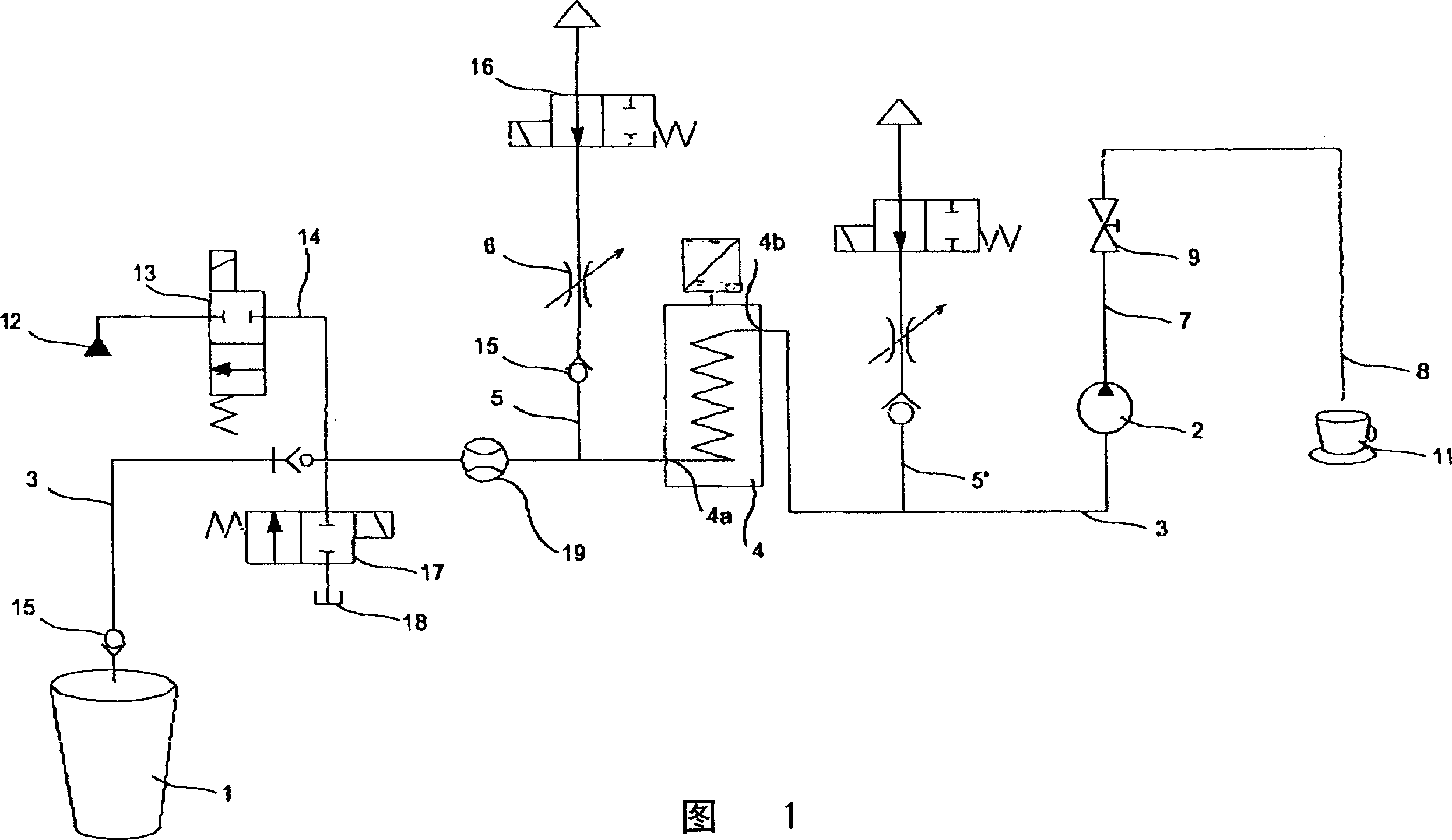
[0015] Fig. 1 shows a container 1 for adorning milk, and various additives, such as chocolate, vanilla, etc., can be added to the milk as required. Cold milk is drawn from the container 1 by means of a pump 2 through a suction pipe 3 and then heated by a continuous flow heater 4 . Reference numeral 4a in FIG. 1 denotes an inlet of the continuous flow heater 4, and reference numeral 4b is an outlet. Before entering the inlet 4a of the continuous flow heater 4, the air supply duct 5 leads to the suction duct 3 to which an adjustable air flow controller 6 is assigned. However, it is also possible to use a fixed nozzle instead of the controller 6 . Through the air supply pipe 5, a certain amount of air can be added to the milk, so that the milk / air mixture (or just milk) can be sucked by the pump 2 and heated in the continuous flow heater 4. In principle, gas mixtures can also be used instead of air.

[0016] On the air supply pipe 5, an active valve 16 can be further designed,...


PUM


Abstract

A device comprises a pump (2) for suctioning milk from a container (1) via a suction line (3); an air supply line (5) connected to an air quantity controller (6); a continuous flow heater (4) located in the suction line; and a throttle valve (9) associated with outlet line (7). The air quantity controller opens into suction line or outlet line. The continuous flow heater takes a labyrinth form and is equipped with a heater element whose temperature is controllable, so that the temperature of the milk or the milk / air mixture can be adjusted. An independent claim is included for the continuous flow heater.

Description

technical field [0001] The invention relates to a method for producing milk froth or a hot milk drink according to claim 1 and a device for applying the method. Background technique [0002] Patent EP-A0600826 discloses a device for generating milk froth. The milk is heated in a container, and the heated milk is sucked by a pump through a suction pipe, and then a certain amount of air is introduced. Milk under pump action, eg a milk / air mixture is delivered to the outlet via the resistive flow element. The container in which the milk is heated must be cleaned regularly because residues build up. Relatively complex resistive flow elements also require thorough and very complex cleaning procedures. Contents of the invention [0003] The object of the present invention is to provide a method as described above, as well as a simple and economical device for applying it, which makes operation and maintenance easier. [0004] This technical problem is solved by the method of ...

Claims


Application Information

Patent Timeline
Patent Type & Authority Applications(China)
IPC IPC(8): A01J11/00A23C9/00A47J31/44A47J43/12
CPCA47J31/4485
Inventor F·迪仁
Owner STEINER WEGGIS AG
Why Eureka
Try Eureka