Rotor for brushless motor and brushless motor

一种无刷电机、转子的技术,应用在带有静止电枢和旋转磁体的同步电动机、电动组件、电气元件等方向,能够解决研磨工序复杂、制造成本增加等问题,达到防止空转和飞散、防止飞散的效果

Inactive Publication Date: 2005-10-19
ICHINOMIYA ELECTRIC
View PDF0 Cites 7 Cited by
  • Summary
  • Abstract
  • Description
  • Claims
  • Application Information

AI Technical Summary

Problems solved by technology

However, in the case where projections, recesses, etc. for engaging with the rotor yoke are formed on the inner circumference of the ring magnet as described above, these projections, etc., must be finished with desired dimensional accuracy, so there is a risk of grinding. The problem that the process becomes complicated and the manufacturing cost increases
[0006] In addition, brushless motors with high output have been used instead of conventional hydraulic motors in elevators, power steering devices of automobiles, etc., but in the above-mentioned brushless motors for conveying passengers, etc., it is necessary to to prevent idling and flying

Method used


Image

  • Rotor for brushless motor and brushless motor
  • Rotor for brushless motor and brushless motor
  • Rotor for brushless motor and brushless motor

Examples


Embodiment Construction

[0023] Embodiments according to the present invention will be described in detail below with reference to the accompanying drawings.

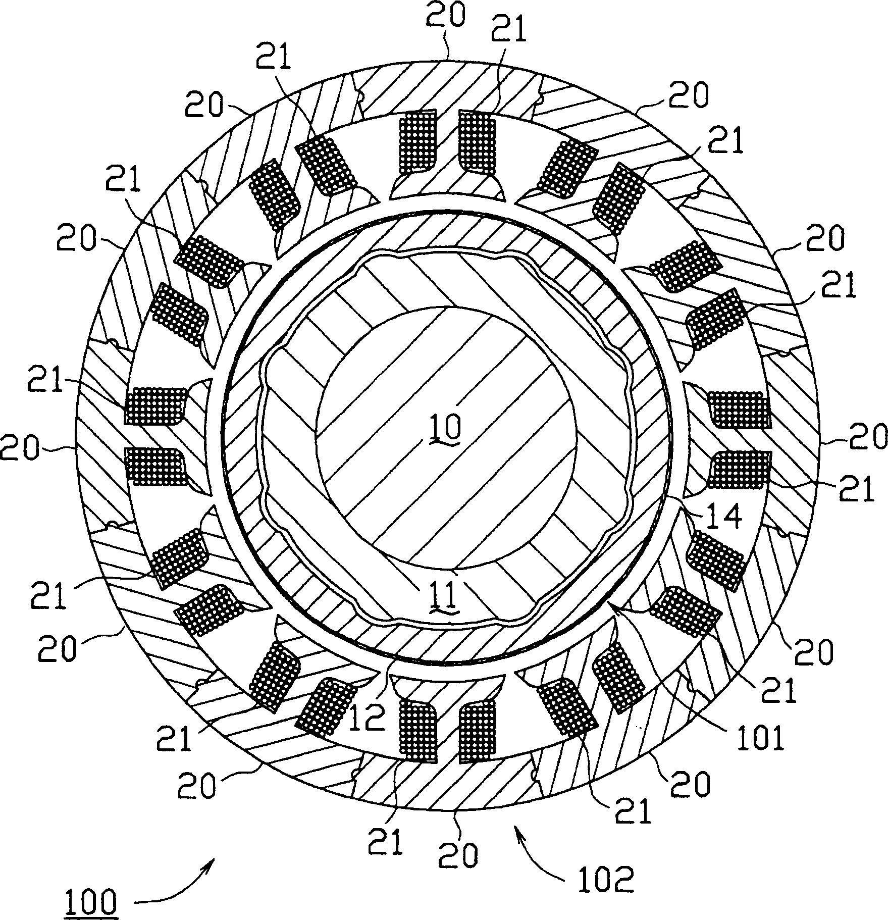
[0024] The brushless motor 100 according to an embodiment of the present invention is an inner rotor type motor having an inner rotor and an outer stator structure. Such as figure 1 As shown in , the inner rotor is composed of a rotor (rotor for a brushless motor) 101, and the outer stator is composed of a stator 102, in which a predetermined number of magnetic cores 20 divided into each tooth are ring-connected together. In the example this number is 12 and a coil 21 is wound on each tooth. The rotor 101 is rotatably provided by forming a fixed gap in the stator 102 .

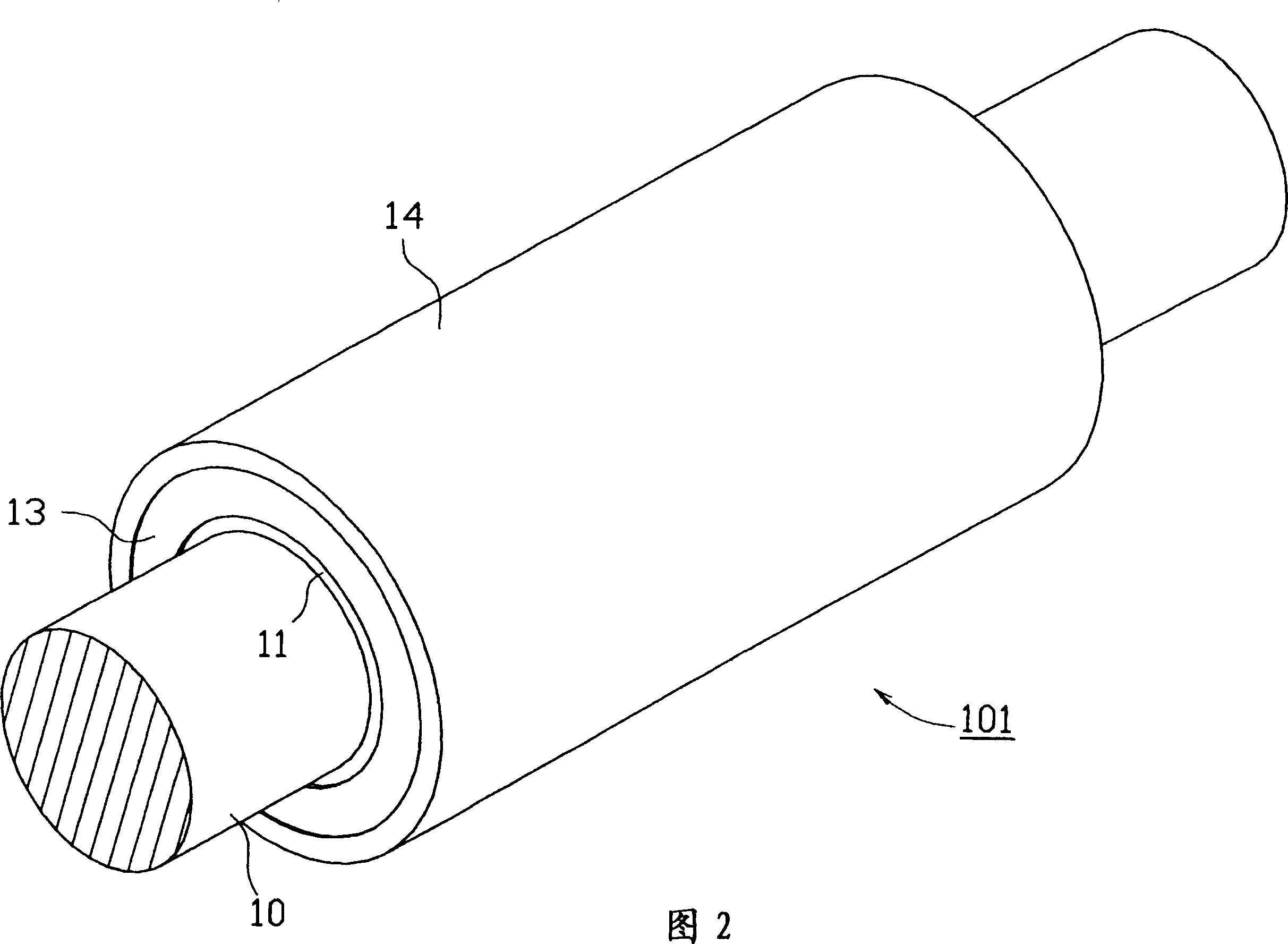
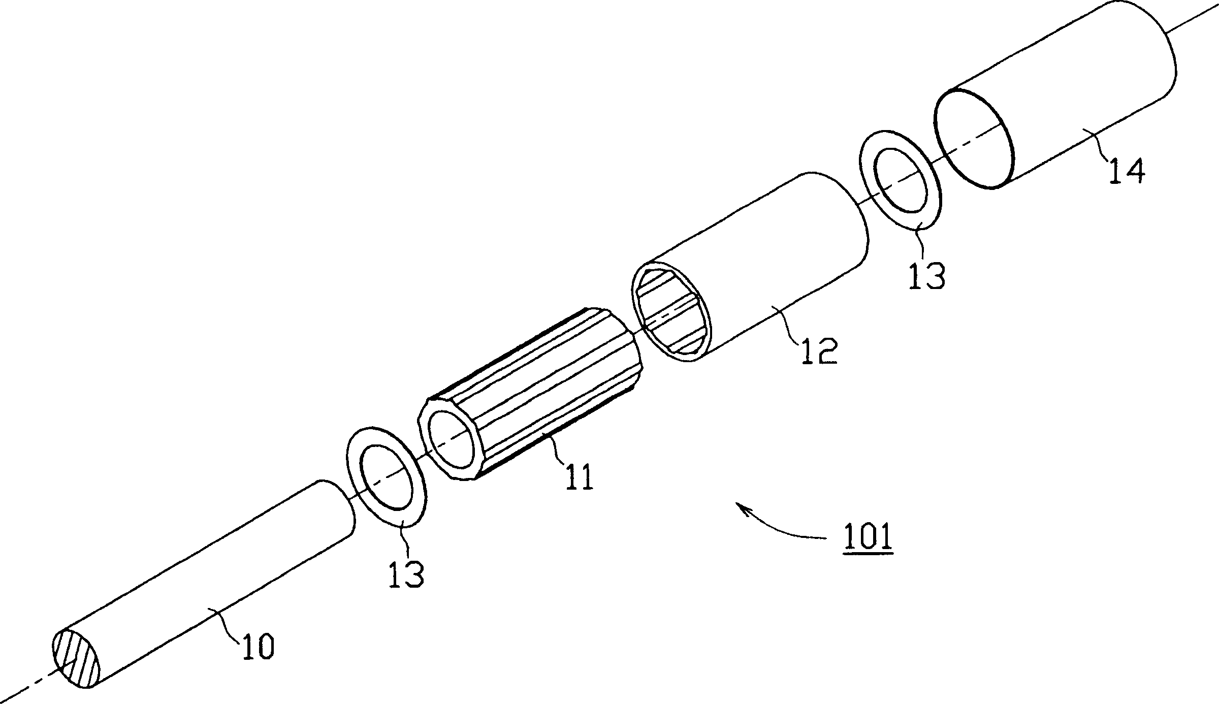
[0025] As shown in FIGS. 2 and 3, the rotor 101 has a shaft 10 forming the shaft of the motor, a rotor yoke 11 provided concentrically on the shaft 10, a sintered ring magnet 12 provided on the outer periphery of the rotor yoke 11, a A protective plate 13 covering two axial ...


PUM


Abstract

The invention provides a means which can securely prevent an idle running and a scattering of a magnet while restricting a manufacturing cost as low as possible, in a rotor used in a brushless motor. A rotor ( 101 ) is provided with a sintered ring magnet ( 12 ) in which not-ground recess portions ( 12 a) are formed in an axial direction of a inner peripheral surface in correspondence to a magnetic pole, and a portion between the recess portions ( 12 a) is ground in an inner peripheral surface ( 12 b) having a desired inner diameter, a rotor yoke ( 11 ) in which convex portion ( 11 b) having a larger diameter than the inner diameter (r 4 ) of the sintered ring magnet ( 12 ) are formed in an axial direction of an outer peripheral surface in correspondence to the recess portion ( 12 a), and a through hole ( 11 a) is pierced in an axial center, and which is concentrically adhered to the sintered ring magnet ( 12 ) by fitting the recess portion ( 12 a) and the convex portion ( 11 b), and a shaft ( 10 ) inserted and fitted to the through hole ( 11 a) of the rotor yoke ( 11 ).

Description

technical field [0001] The present invention relates to a structure of a rotor for a brushless motor (motor) having a sintered ring magnet. Background technique [0002] Various motors such as induction motors, rectifier motors, etc. are generally used as motors, but in recent years brushless motors with high performance are often used. In an inner rotor type brushless motor as one of the brushless motors, magnets (magnets) are arranged on the outer periphery of a rotor forming an inner rotor, and are fixed to a rotor yoke by an adhesive. The magnet includes a so-called segmented type (magnet) in which a plurality of magnet pieces are arranged in the circumferential direction corresponding to the number of poles of the brushless motor, and a magnet formed in a cylindrical shape and magnetized in multipoles in the circumferential direction. ring magnet. However, in segmented magnets, an increase in temperature weakens the bonding strength, and there is a danger of the magne...

Claims


Application Information

Patent Timeline
Patent Type & Authority Applications(China)
IPC IPC(8): H02K29/00H02K1/27H02K7/00H02K21/14
CPCH02K1/2733
Inventor 木梨好一中尾雅俊
Owner ICHINOMIYA ELECTRIC
Why Eureka
Try Eureka