Power transmission belt and method of producing the same

a technology of power transmission belt and transmission belt, which is applied in the field of power transmission belt, can solve the problems of low work precision of the element, high production cost of the power transmission belt, and short so as to reduce the production cost of the element, improve the life expectancy of the press working mold, and improve the quality of the elemen

Active Publication Date: 2013-05-28
TOYOTA JIDOSHA KK
View PDF24 Cites 6 Cited by
  • Summary
  • Abstract
  • Description
  • Claims
  • Application Information

AI Technical Summary

Benefits of technology

[0036]The power transmission belt according to the present invention allows the material of the element to be pressed and held on the both surfaces thereof in the area parallel to each other in the vicinity of the concave-convex portion to perform the precise forming to the concave-convex portion with excellent precision and the life expectancy of the press working mold to be extended even if the concave-convex portion and the rocking edge portion are close together. Therefore, the power transmission belt according to the present invention can reduce the production cost of the element, and thus can be produced at a low cost while maintaining the work precision of the element.
[0037]The method of producing a power transmission belt according to the present invention can enhance the work precision of the element and the life expectancy of the press working mold, resulting from the fact that the material forming step is carried out in such a manner that the curved inclination surface is formed in the step portion between the first plate thickness portion and the second plate thickness portion to be inclined having a large maximum inclination angle from the gentle inclination surface and with the inclination angle being reduced toward the second plate thickness portion, and the press forming step is then carried out in such a manner that the pressing and holding area can be secured in the vicinity of the concave-convex portion, while suppressing the plastic deformation amount of the material for forming the rocking edge portion and the concave-convex portion, thereby making it possible to enhance the work precision of the element and the life expectancy of the press working mold. It is therefore possible to materialize the production method, which can suppress the production cost of the element while maintaining the work precision of the element.

Problems solved by technology

However, they are disadvantageous in that the work precision of the element is decreased and the life expectancy of the press working mold becomes short, thereby causing such a problem that the power transmission belt becomes high in production cost.
However, it is difficult to reliably press and hold the sheet-metal material between the punch and the counter punch, resulting from the concave and convex portions and the inclination surface arranged adjacent to each other, thereby causing the work precision of the element to be decreased and shortening the life expectancy of the mold used for the press work.

Method used


Image

  • Power transmission belt and method of producing the same
  • Power transmission belt and method of producing the same
  • Power transmission belt and method of producing the same

Examples


first embodiment

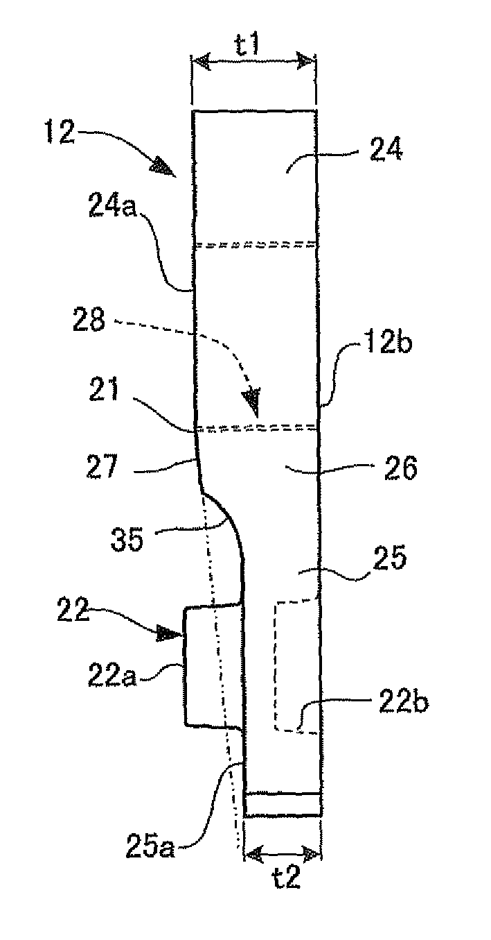
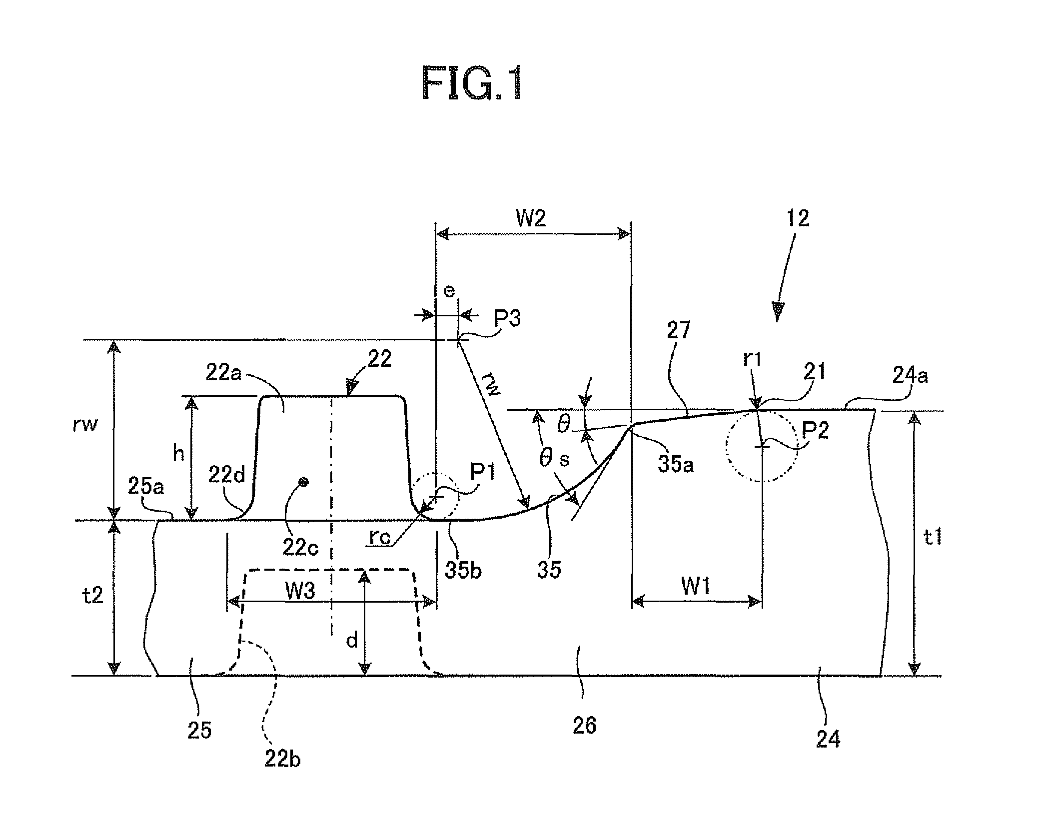
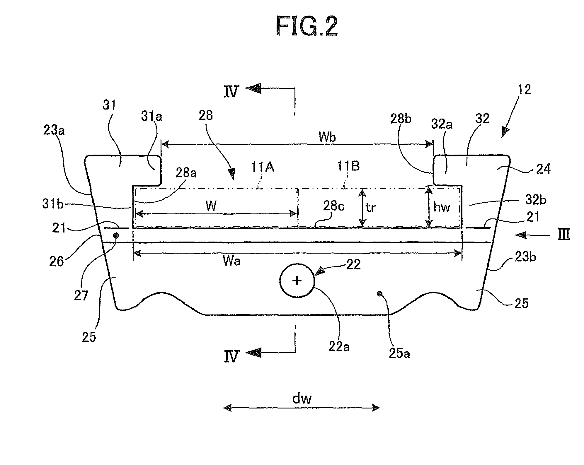
[0053]FIGS. 1 to 6B are outlined block construction views showing the power transmission belt and the shape of its elements forming part of the power transmission belt according to the first embodiment of the present invention, and illustrating an example of the present invention applied to the power transmission belt of the belt type continuously variable transmission of an automotive vehicle.

[0054]Firstly, the construction of the power transmission belt according to the first embodiment of the present invention will be described hereinafter.

[0055]As shown in FIG. 5, the power transmission belt 10 according to the present embodiment is made of metal and provided within a continuously variable transmission 1 (its detail not shown). The continuously variable transmission 1 is constructed to include a primary pulley 2 (drive side pulley) drivably connected with an input shaft not shown, a secondary pulley 3 (driven side pulley) drivably connected with an output shaft also not shown, a...


PUM

PropertyMeasurementUnit
thicknessaaaaaaaaaa
thicknessaaaaaaaaaa
thicknessaaaaaaaaaa

Abstract

A power transmission belt low in cost and preventing work precision from being lowered and life expectancy of a metal press working mold from being decreased and a method of producing such a power transmission belt are provided. The power transmission belt includes endless band-like rings, and a plurality of elements bonded into an annular shape by the endless band-like rings. Each of the elements has both side end surface portions pressed between pulleys in the belt width direction, a rocking edge portion serving as a fulcrum when rocked in the state that the elements are partly wound around the pulleys, and a concave-convex portion engageable in concave-convex engagement with the concave-convex portions of a pair of neighboring elements. Each of the elements is formed with a curved inclination surface between the rocking edge portion and the concave-convex portion to have an inclination angle reduced toward the concave-convex portion.

Description

TECHNICAL FIELD[0001]The present invention relates to a power transmission belt and a method of producing the same, and in particular to a power transmission belt preferable for a belt type continuously variable transmission and a method of producing the same.BACKGROUND ART[0002]There has so far been known a belt type power transmission apparatus as a vehicular continuously variable transmission (hereinafter simply referred to as “CVT”). The belt type power transmission apparatus comprises a drive side pulley and a driven side pulley respectively serving as movable sheaves, and an endless power transmission belt wound around the drive side pulley and the driven side pulley. The power transmission belt to be used for such a CVT is constituted by an endless band-like ring serving as a core material, and a multiplicity of elements each having a predetermined thickness in the axial direction of the endless band-like ring and retained by the endless band-like ring. The elements are subje...

Claims


Application Information

Patent Timeline
Patent Type & Authority Patents(United States)
IPC IPC(8): F16G5/16
CPCF16G5/16Y10T29/49838
Inventor MORINO, TAKUROYOSHIDA, MICHIO
Owner TOYOTA JIDOSHA KK
Why Eureka
Try Eureka