Wafer level lens, production method of wafer level lens, and imaging unit

a production method and technology applied in the field of wafer level lens, can solve the problems of increasing the production cost corresponding to this process, affecting the quality of the lens, so as to prevent the generation of light transmission and reflection at a region other than the lens surface, and prevent the transmission of light

Active Publication Date: 2014-09-04
FUJIFILM CORP
View PDF2 Cites 5 Cited by
  • Summary
  • Abstract
  • Description
  • Claims
  • Application Information

AI Technical Summary

Benefits of technology

[0010]Originally, the wafer level lens has a big profit of suppressing production cost since a plurality of lenses are simultaneously molded on a substrate, and the substrate is diced and connected to a semiconductor substrate carrying thereon an imaging device, and the like. However, if a light shielding member is separately attached, an increase in the production cost corresponding to this process is inevitable.
[0027]The present invention is capable of providing a wafer level lens with which a sufficient light shielding property is obtained, generation of defects such as ghosts, flares and the like due to a reflected light can be prevented, and an increase in the production cost can be suppressed; a production method of a wafer level lens, and an imaging unit.

Problems solved by technology

Owing to this constitution, if a wafer level lens is diced and placed on an imaging device to give an imaging unit and when light transmission and reflection occur at a region other than the lens surface of the lens, there is a fear of tendency of defects in optical performances such as ghosts and flares in taking an image.
However, if a light shielding member is separately attached, an increase in the production cost corresponding to this process is inevitable.

Method used


Image

  • Wafer level lens, production method of wafer level lens, and imaging unit
  • Wafer level lens, production method of wafer level lens, and imaging unit
  • Wafer level lens, production method of wafer level lens, and imaging unit

Examples


Embodiment Construction

[0042]First, the constitutions of a wafer level lens and an imaging unit will be explained.

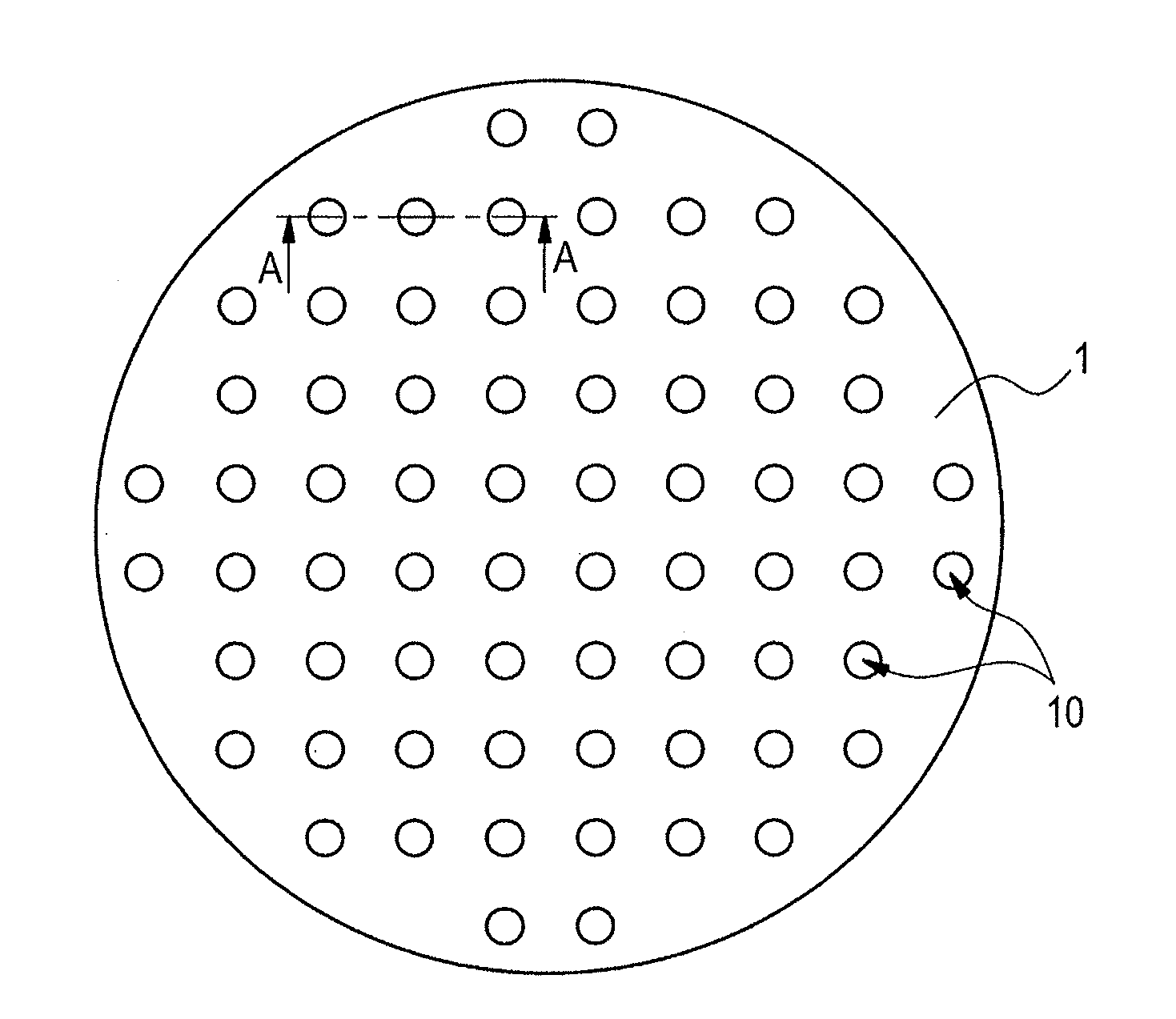
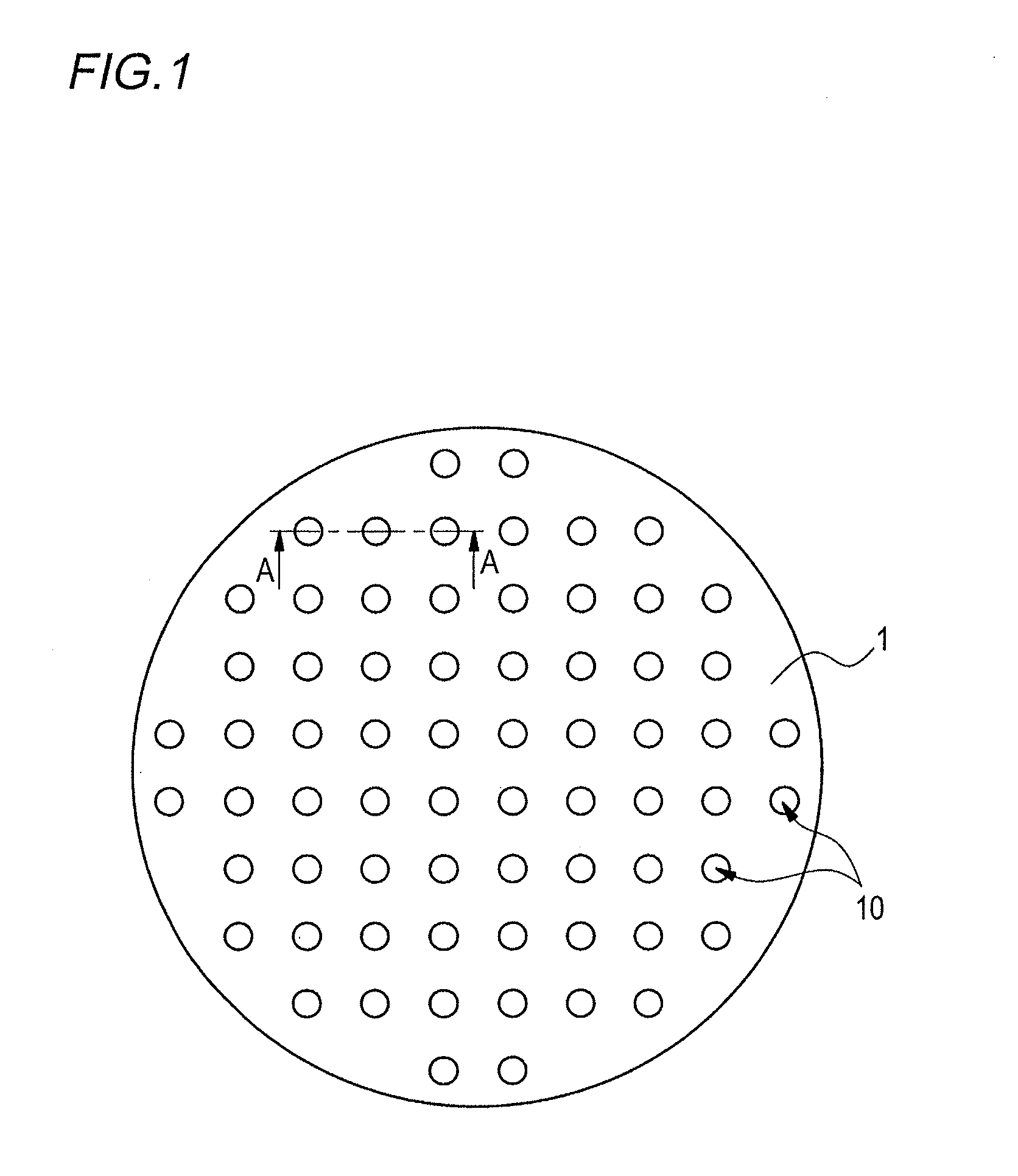
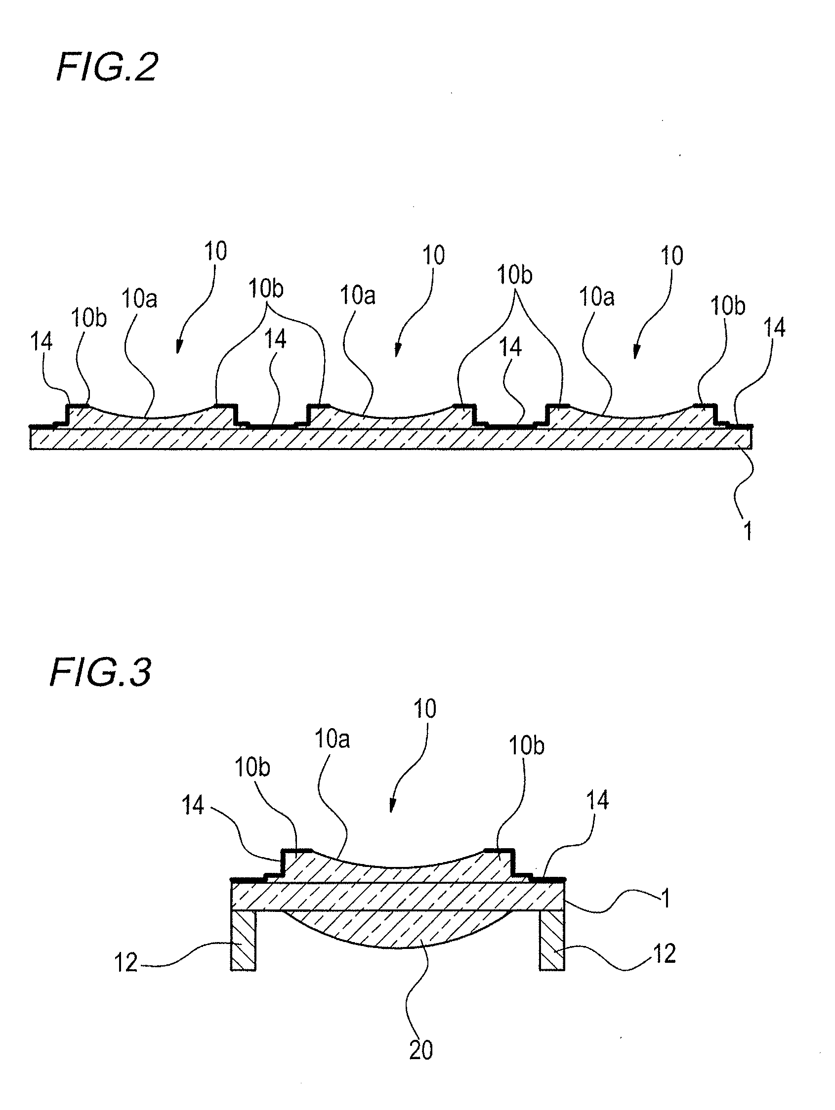
[0043]FIG. 1 is a plane view showing one example of the constitution of a wafer level lens. FIG. 2 is a cross-sectional view taken in a line A-A of the constitution of the wafer level lens shown in FIG. 1.

[0044]The wafer level lens has a lens module having a substrate 1 and a plurality of lenses 10 formed on the substrate 1. The plurality of lenses 10 are arranged on the substrate 1 in one-dimensional mode or two-dimensional mode. In this constitution example, an example of a constitution in which the plurality of lenses 10 are arranged on the substrate 1 in two-dimensional mode as in FIG. 1 will be explained. The lens 10 is constituted of the same material as for the substrate 1, and molded on the substrate 1.

[0045]As shown in FIG. 2, the lens 10 has a concave-shaped lens surface 10a and a lens marginal part 10b around the lens surface 10a. Here, the lens surface 10a has an optical property o...


PUM

PropertyMeasurementUnit
transmittanceaaaaaaaaaa

Abstract

A sufficient light-shielding property is obtained by a wafer level lens having at least one lens module having a substrate and a plurality of lenses formed on the substrate in which the wafer level lens has a black resist layer formed on the surface of the lens module or on the surface of the substrate and the black resist layer is formed with a pattern having an opening at a part intersecting the optical axis of the lens, and generation of defects such as ghosts, flares and the like due to a reflected light can be prevented and an increase in the production cost can be suppressed.

Description

[0001]This is a Divisional Application of U.S. application Ser. No. 13 / 390,191, filed Feb. 13, 2012, which is a National Stage Entry of PCT / JP2010 / 063686 filed Aug. 12, 2010, which claims priority under 35 U.S.C. §119, from JP Application Nos. 2009-187858, filed Aug. 12, 2009; JP 2009-208365, filed Sep. 9, 2009; JP 2009-208366, filed Sep. 9, 2009; JP 2009-208367, filed Sep. 9, 2009; JP 2010-180625 filed Aug. 11, 2010; JP 2010-180626, filed Aug. 11, 2010; JP Application No. 2010-180627 filed Aug. 11, 2010 and JP 2010-180628 filed Aug. 11, 2010, the disclosures of which are incorporated herein by reference.TECHNICAL FIELD[0002]The present invention relates to a wafer level lens, a production method of a wafer level lens, and an imaging unit.BACKGROUND ART[0003]Presently, a portable terminal of electronic instruments such as cellular phones, PDAs (Personal Digital Assistants) and the like is loaded with a small and thin imaging unit. Such an imaging unit is generally equipped with a so...

Claims


Application Information

Patent Timeline
Patent Type & Authority Applications(United States)
IPC IPC(8): G02B1/11B29D11/00G02B13/00H01L27/146
CPCG02B1/11G02B13/0085B29D11/00009H01L27/14627G02B3/0031G02B7/022G02B13/001B29D11/00307B29D11/00G02B13/18H01L27/146H04N23/00
Inventor MARUYAMA, YOICHI
Owner FUJIFILM CORP
Why Eureka
Try Eureka