Portable terminal

a terminal and portability technology, applied in the field of portability terminals, can solve problems such as deteriorating display quality, and achieve the effects of preventing the display quality of the display panel from deteriorating, and reducing the cost of heat radiation from electronic components

Active Publication Date: 2015-06-18
SHARP KK
View PDF25 Cites 7 Cited by
  • Summary
  • Abstract
  • Description
  • Claims
  • Application Information

AI Technical Summary

Benefits of technology

[0011]According to the present invention, the heat generated from the electronic component travels from the circuit board to the rechargeable battery. The rechargeable battery has the large heat capacity, and the heat traveling to the rechargeable battery is stored into the rechargeable battery and diffused. In this way, the rechargeable battery shuts down the heat traveling from the electronic component to the display panel to prevent the display quality of the display panel from deteriorating. Besides, it is possible to efficiently perform the heat radiation from the electronic component and curb performance deterioration of the electronic component. Besides, it becomes possible to perform the heat radiation from the electronic component by using the rechargeable battery and curb the production cost of the portable terminal.

Problems solved by technology

However, the electronic component generates heat during use of the portable terminal; accordingly, there is a problem that the heat generated from the electronic component locally travels to the display panel to deteriorate display quality.

Method used


Image

  • Portable terminal
  • Portable terminal
  • Portable terminal

Examples


Embodiment Construction

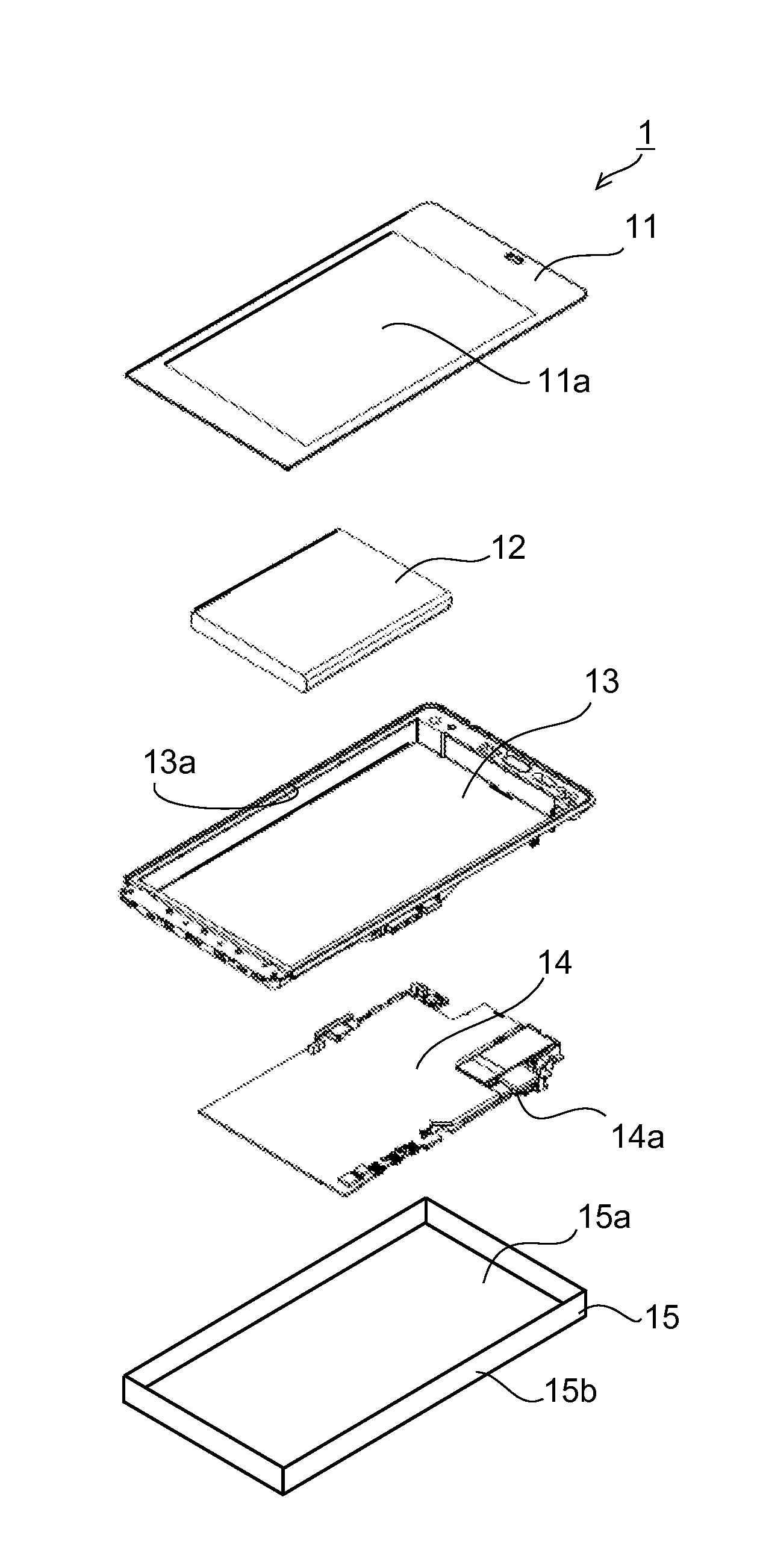
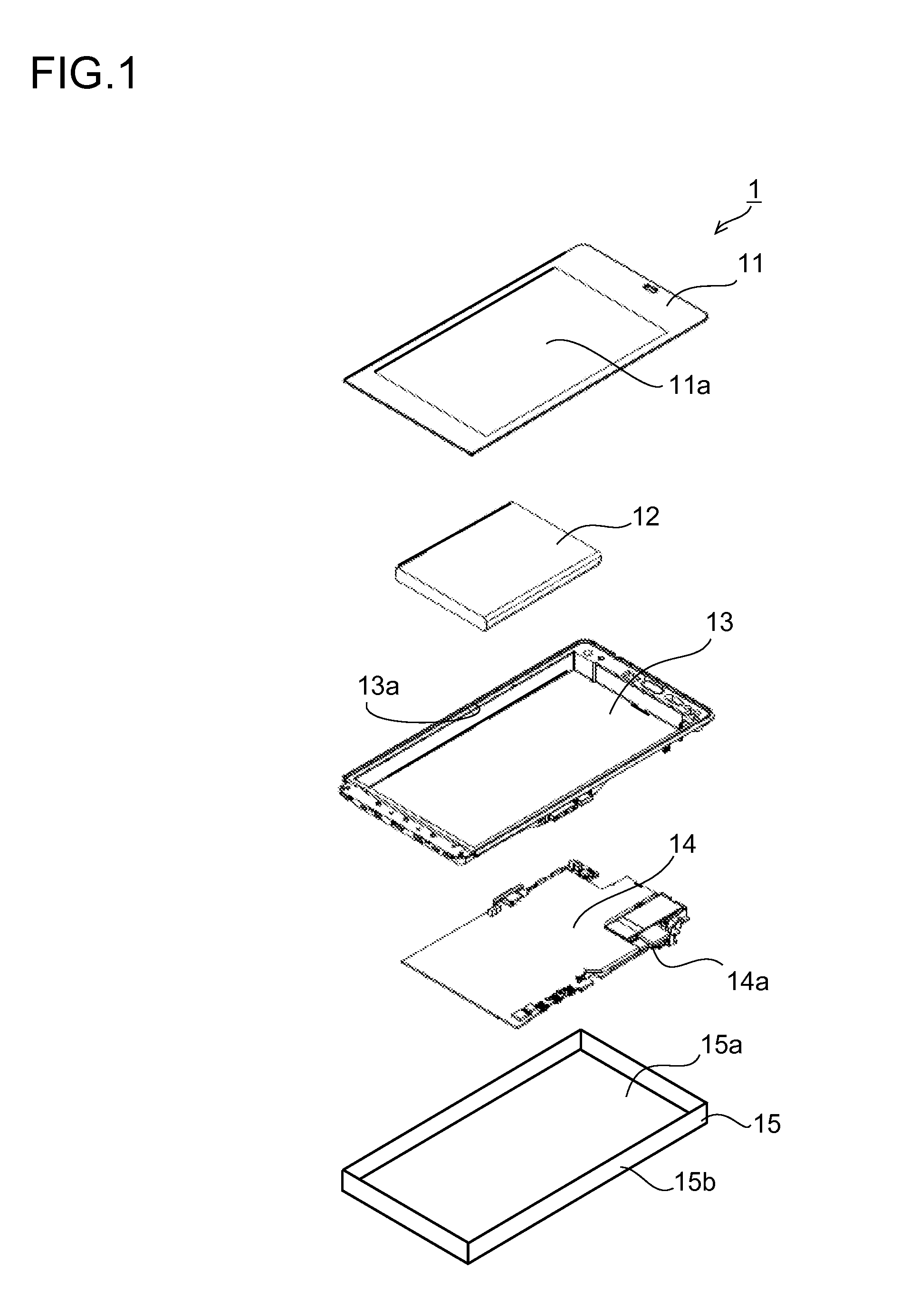
[0014]Hereinafter, the present invention is described based on drawings that show an embodiment. FIG. 1 is an exploded perspective view of a portable terminal 1 according to an embodiment of the present invention.

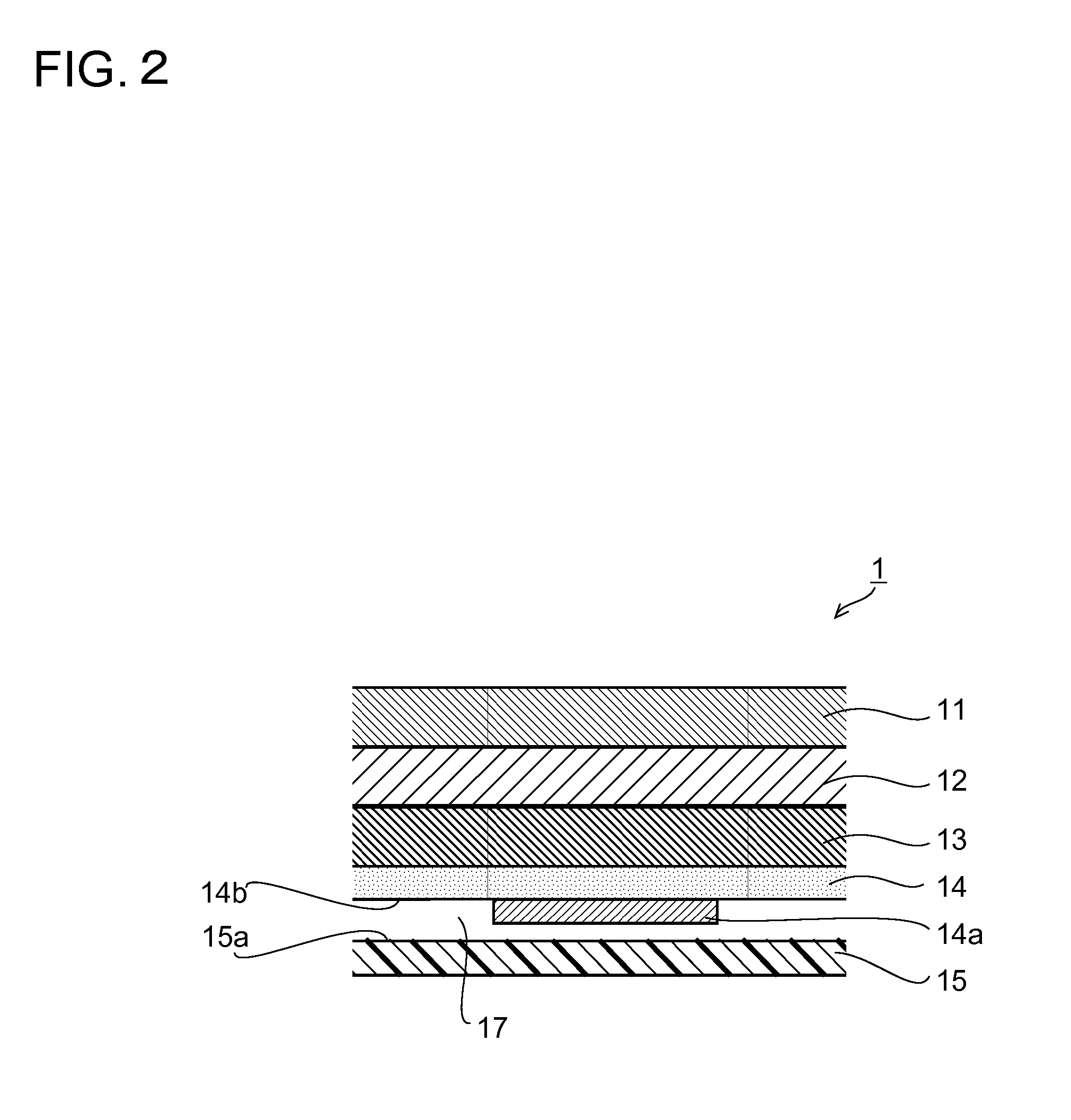
[0015]A surface of the portable terminal 1 is provided with a display panel 11 and a rear side is covered by a cabinet 15. The cabinet 15 is formed of a metal such as aluminum or the like, and is provided with a circumferential wall 15b erected from a circumferential edge of a bottom surface 15a to have a box shape with an upper surface opened. The cabinet 15 houses therein a circuit board 14, a metal plate 13, and a rechargeable battery 12.

[0016]As to the circuit board 14, an electronic component 14a is mounted on a mount surface 14b, and the mount surface 14b is disposed to oppose the bottom surface 15a of the cabinet 15. The electronic component 14a has heat generating components such as a CPU (Central Processing Unit), a wireless circuit component, a rechargeable circui...


PUM


Abstract

This portable terminal has disposed therein: a circuit board (14), which is disposed in a cabinet (15), and which has an electronic component (14a) mounted thereon; a display panel (11) disposed on the open plane of the cabinet (15); and a rechargeable battery (12) disposed between the display panel (11) and the circuit board (14).

Description

TECHNICAL FIELD[0001]The present invention relates to a portable terminal that efficiently radiates heat generated from an electronic component.BACKGROUND ART[0002]A general portable terminal includes: a display panel; a circuit board on which an electronic component is mounted; and a rechargeable battery that supplies power to the circuit board and the display panel. Besides, the circuit board and the rechargeable battery are housed in a cabinet, and the display panel is disposed on an open surface of the cabinet. Here, the circuit board is disposed on a rear side of the display panel, and the rechargeable battery is disposed on a rear side of the circuit board. And, the electronic component and the display panel operate on the power supplied from the rechargeable battery. However, the electronic component generates heat during use of the portable terminal; accordingly, there is a problem that the heat generated from the electronic component locally travels to the display panel to ...

Claims


Application Information

Patent Timeline
Patent Type & Authority Applications(United States)
IPC IPC(8): H05K7/20H05K7/14
CPCH05K7/1422H05K7/20509H05K7/20445H04M1/0262H04M1/0266H04M1/0277G06F1/1626G06F1/203
Inventor UENO, TAKASHIMIYAUCHI, YASUMASA
Owner SHARP KK
Why Eureka
Try Eureka