

Magnetic bearing device and magnetic bearing spindle device
- Summary
- Abstract
- Description
- Claims
- Application Information
AI Technical Summary
Benefits of technology
Problems solved by technology
Method used
Image

Examples
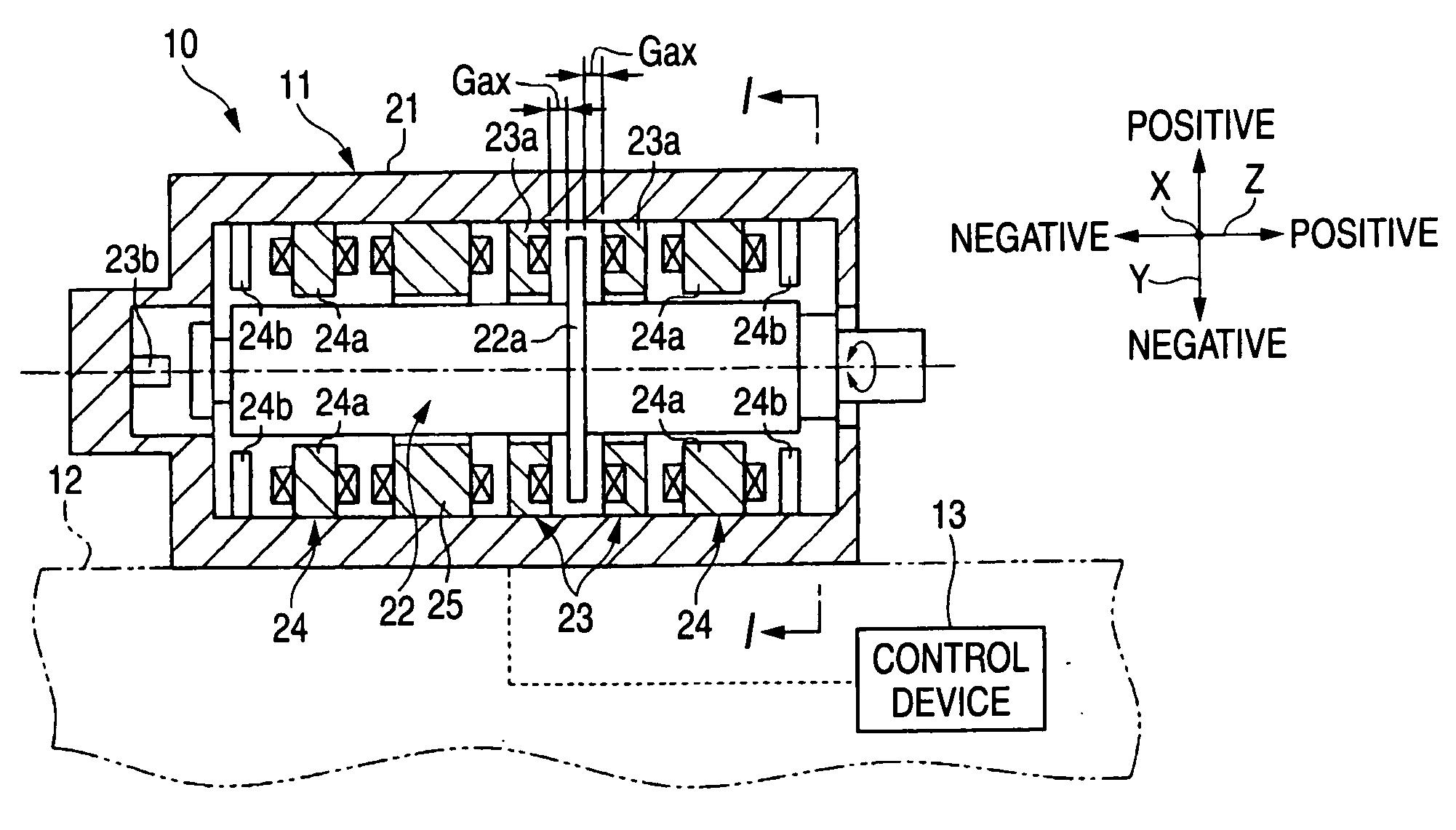
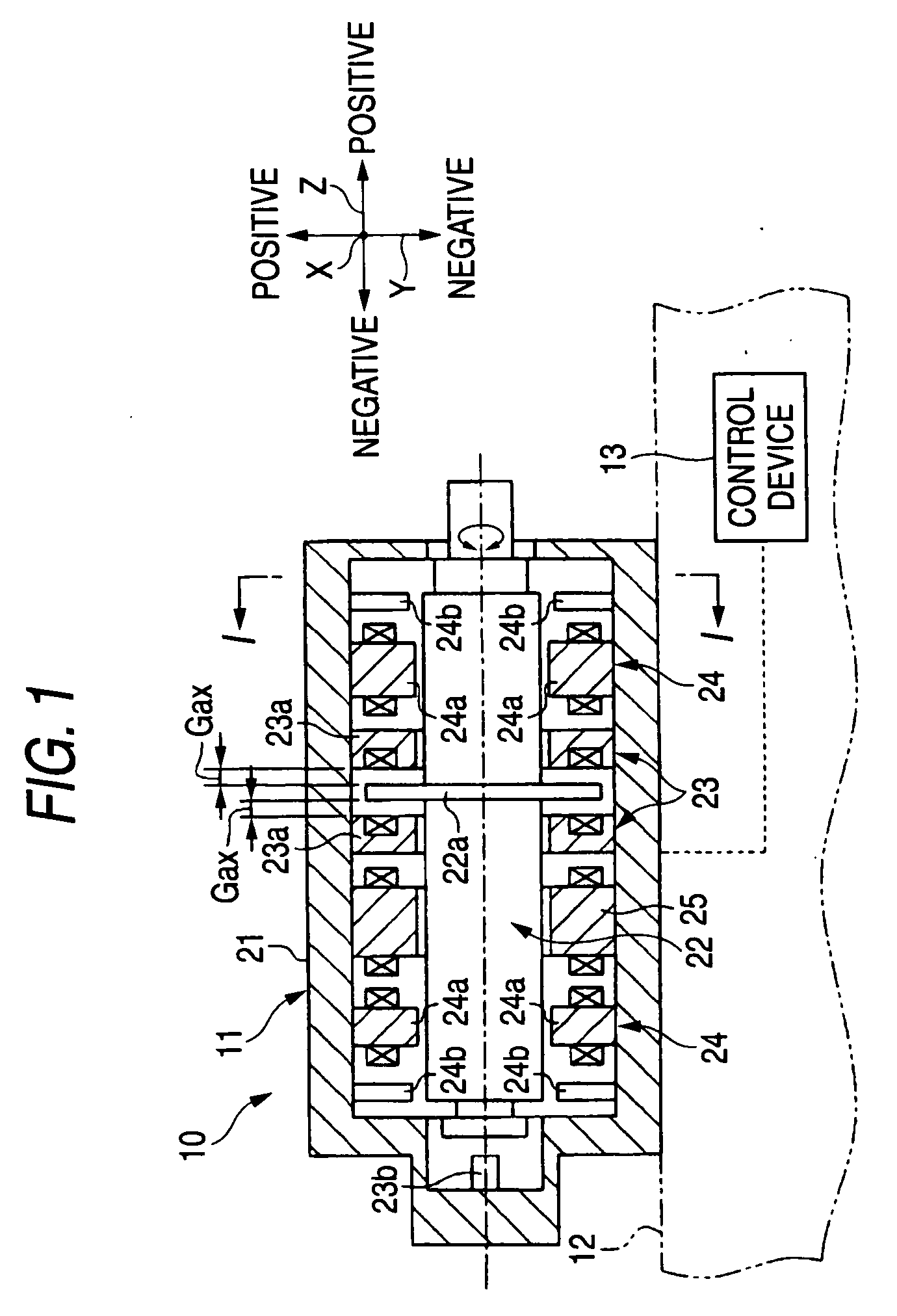
embodiment
Effect of Embodiment
[0071]Accordingly, the following effect can be obtained according to the present embodiment.
[0072](1) The control device 13 includes the differential amplifying circuit 43 as the calculator for obtaining the difference between the voltage values V1 and V2 corresponding to the exciting currents supplied to a pair of axial electromagnets 23a and a pair of radial electromagnets 24a and multiplying the difference (=V1−V2) by coefficients (“R3 / R1” times) to obtain the bearing load in the radial direction and the axial direction. The operation for obtaining the difference between the voltage values corresponding to the exciting currents supplied to a pair of axial electromagnets 23a and a pair of radial electromagnets 24a and multiplying the difference by the coefficients is similar to the operation for obtaining the difference between the values of the exciting currents supplied to a pair of axial electromagnets 23a and a pair of radial electromagnets 24a and multiply...
PUM
 Abstract
Description
Claims
Application Information