
Thermal head and thermal printer using the same

Inactive Publication Date: 2008-09-18
SEIKO INSTR INC
View PDF1 Cites 5 Cited by
  • Summary
  • Abstract
  • Description
  • Claims
  • Application Information

AI Technical Summary

Benefits of technology

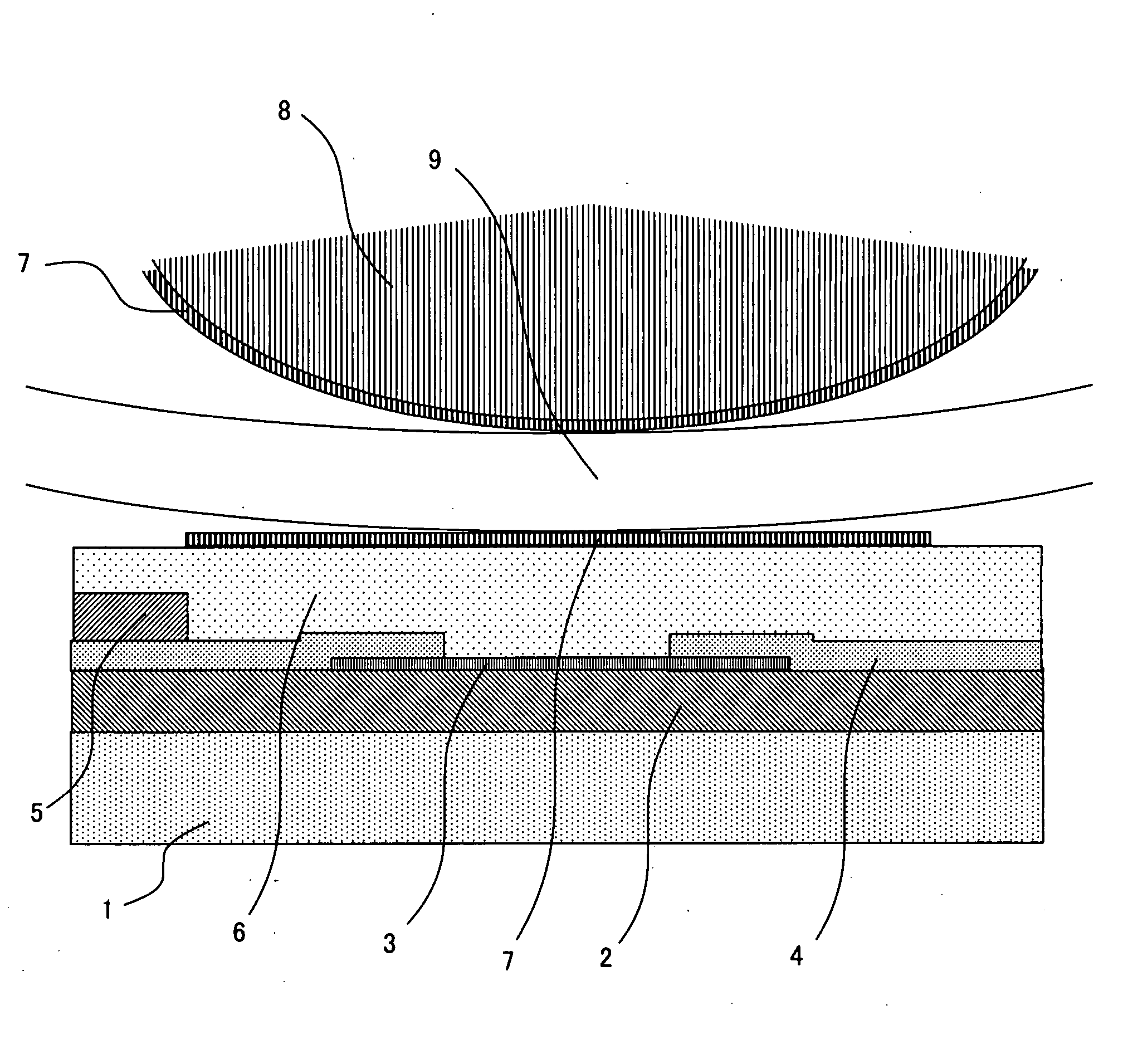
[0013] As a result, on a surface of the thermal head, there is formed the resin covering layer formed of the fluorine-based resin particles having an antifouling effect and a small coefficient of friction. Accordingly, the thermal head and the platen roller are prevented from sticking together due to the long-term preservation.
[0014] Further, the fluorine-based resin particles merely adhere onto the protective film of the thermal head with a weak adhesion force, so when recording paper is conveyed for the first time, the resin covering layer is easily removed from a heater element portion. Thus, after that, the fluorine-based resin particles do not affect the print quality of the thermal printer.
[0015] According to the present invention, in the thermal head, in which a large number of heat generating resistance layers are aligned on a substrate and the large number of heat generating resistance layers are covered with a protective film formed of an inorganic material, a resin covering layer formed of a fluorine-based resin adheres onto a surface of the protective film. Accordingly, due to properties of the fluorine-based resin forming the resin covering layer, including an antifouling effect and a small coefficient of friction, the thermal head and the platen roller do not stick to each other. Thus, with the thermal printer, in which a thermal head and a platen roller cannot be spaced apart from each other, it is possible to convey recording paper in a stable manner even after the long-term preservation.
[0016] Further, the fluorine-based resin particles are applied onto the protective film while being dissolved in a solvent. Therefore, adhesion of the fluorine-based resin particles is achieved only with a weak adhesion force, so when the recording paper is conveyed for the first time, the resin cove ring layer is easily removed from a heater element portion. Consequently, after that, the fluorine-based resin particles do not affect the print quality of the thermal printer in which heat generation of the thermal head and conveyance of recording paper are repeated.
[0017] Moreover, according to a method of the present invention, onto a surface of the thermal head, the fluorine-based resin particles dissolved in a volatile solvent is applied and are then merely air-dried at normal temperature, so it is possible to perform covering remarkably easily as compared to a method involving a heat treatment or the like. Thus, it is possible to markedly suppress production costs.

Problems solved by technology

However, a thermal head according to the above-related art, in some cases, cannot meet demands of a thermal printer including a mechanism to be described below.
However, in the thermal printer having the structure in which the thermal head and the platen roller cannot be spaced apart from each other, in a case where the thermal printer is preserved for a long period of time in a state where no recording medium is provided therein after shipment from a factory, or the like, the platen roller generally made of a rubber material may stick to the protective film of the thermal head to be fixed thereto.
Further, when an entire surface of a heater element portion is covered with a resin covering layer, there is a strong possibility of affecting heat generation of the thermal head, thereby deteriorating a print quality.

Method used


Image

  • Thermal head and thermal printer using the same
  • Thermal head and thermal printer using the same
  • Thermal head and thermal printer using the same

Examples


Embodiment Construction

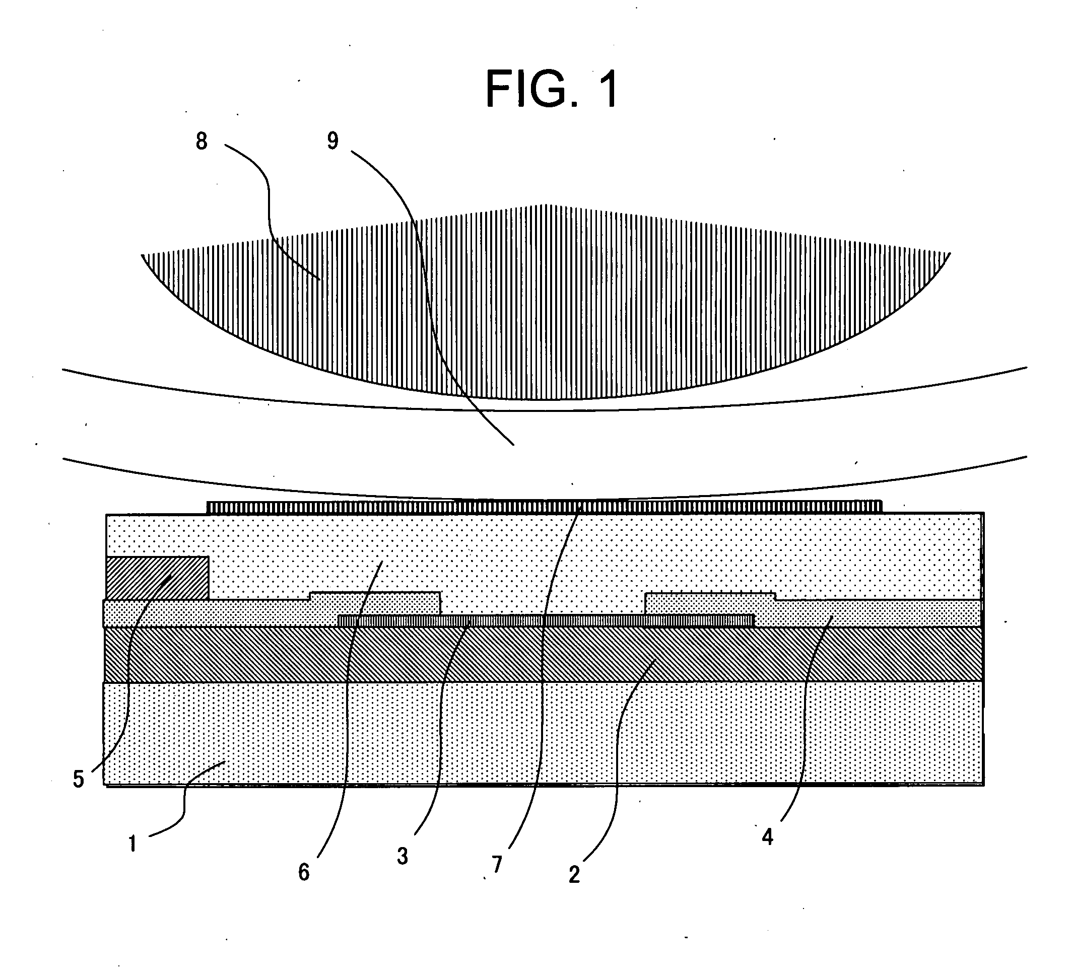
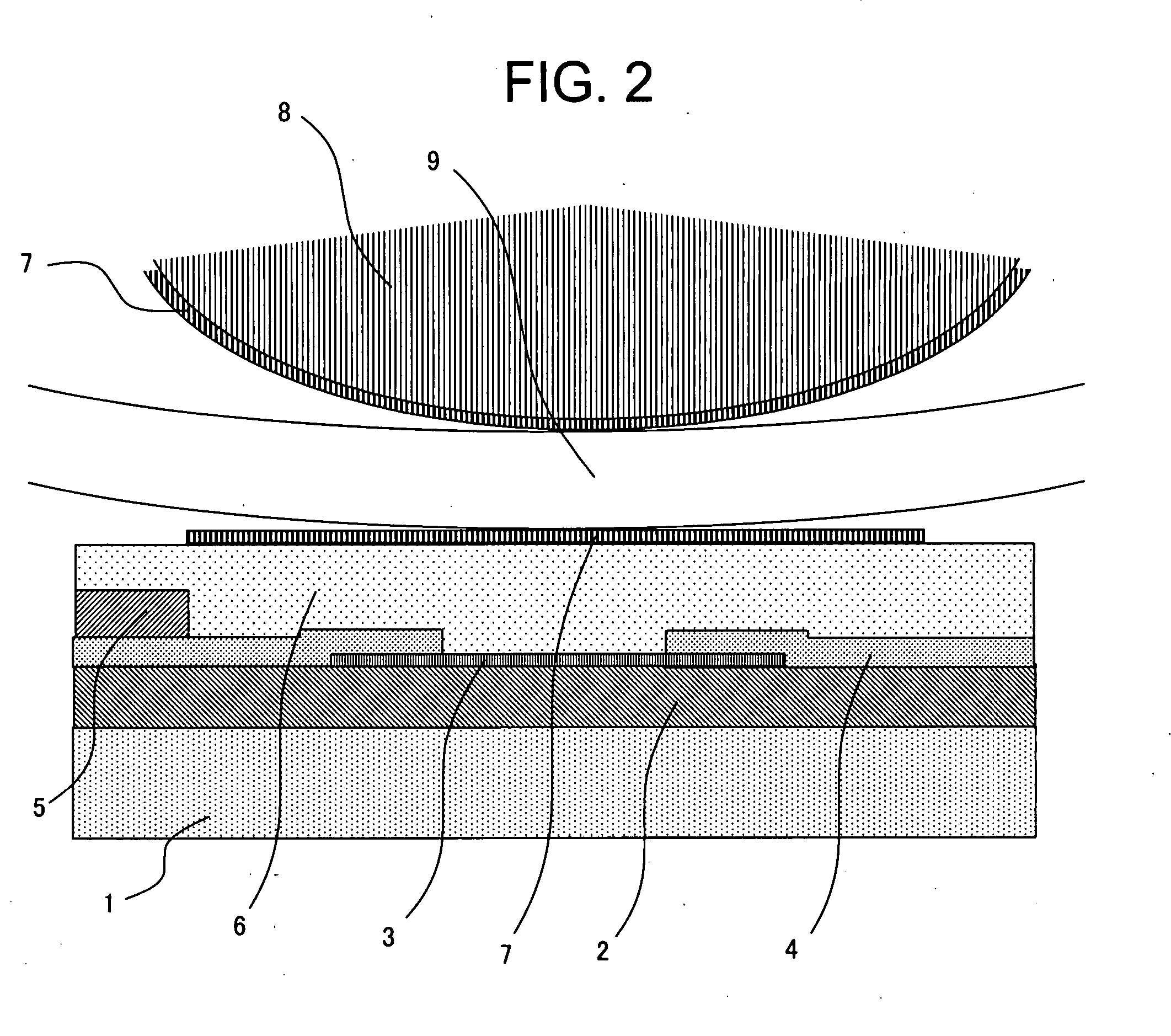
[0021] Hereinafter, the present invention will be described in detail with reference to the drawings. FIG. 1 is a sectional view of a thermal head and a platen roller of a thermal printer according to an embodiment of the present invention. FIG. 2 is a sectional view of a thermal head and a platen roller of a thermal printer according to another embodiment of the present invention.

[0022] A substrate 1 is an insulating substrate such as an alumina ceramics substrate typically used for the thermal head. In a case where the alumina ceramics substrate is used, on the substrate 1, there is formed a heat storage layer 2 of glass or the like for making calorie of a heat generating resistance layer 3, which has generated heat, be difficult to be discharged to the substrate.

[0023] Hereinafter, a thermal head formed by a thin film process will be used as an example for describing the present invention in detail. On the heat storage layer 2, by a thin film forming methods such as sputtering,...


PUM


Abstract

A thermal head has a heat storage layer provided on an insulating substrate and a heat generating resistance layer provided on the heat storage layer. An individual electrode and a common electrode are formed on the heat generating resistance layer, and a protective film layer covers the electrodes and the heat generating resistance layer. A resin covering layer is formed on the surface of the protective film layer by applying and drying fluorine-based resin particles dissolved in a solvent on the surface.

Description

[0001] This application claims priority to Japanese Patent Application No. 2006-049704 filed Feb. 27, 2006, the entire content of which is hereby incorporated by reference. BACKGROUND OF THE INVENTION [0002] The present invention relates to a thermal head used as a printing element for a facsimile, a receipt printer, or the like and a thermal printer using the same, and more particularly, to a thermal printer of a type in which the thermal head and a platen roller serving as a recording medium feed mechanism member come into close contact with each other at all times and cannot be separated. [0003] A thermal head is used as the printing element for thermal recording or thermal transfer recording performed by a facsimile, a receipt printer, or the like. [0004] As a conventional thermal head, for example, as shown in FIG. 3, there has been known one having a structure in which on an upper surface of a heat storage layer 2 formed on a substrate 1, the heat storage layer 2 being formed ...

Claims


Application Information

Patent Timeline
IPC IPC(8): B41J2/335B41J2/34
CPCB41J2/3355B41J2/3353
Inventor SHOJI, NORIYOSHISATO, YOSHINORISUZUKI, HIROKAZU
Owner SEIKO INSTR INC
Learn More