
Tray type CD-ROM

A tray-type, optical drive technology, applied in the direction of recording information storage, instruments, etc., can solve the problems of restrained discs, broken fragments, user hazards, etc.

Inactive Publication Date: 2005-11-02
QUANTA STORAGE INC
View PDF0 Cites 0 Cited by
  • Summary
  • Abstract
  • Description
  • Claims
  • Application Information

AI Technical Summary

Problems solved by technology

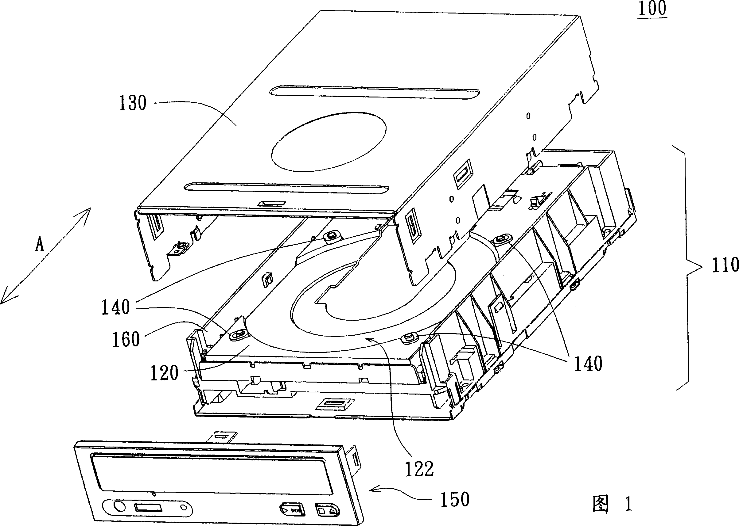
[0005] However, the above-mentioned tray 120 and movable holder 140 cannot fully constrain the disk.
Therefore, when the disk enters and leaves the machine vertically, it is easy to cause the data surface of the disk to be scratched
And because the user has to manually toggle the movable holder 140 to fix the disc to the correct position for inserting the disc, it is inconvenient to use
Furthermore, the setting of the movable holder 140 will increase the material cost and assembly cost
[0006] In addition, if the optical disc is flawed, when the optical disc is accessed by the tray-type optical drive 100 in a high-speed rotating manner in the tray-type optical drive 100, it may be broken and become fragments.
Therefore, the high-speed and scattered disc fragments (broken disc) are very likely to collide with the panel 150, causing the panel 150 to be deformed, even in the gap between the disc fragments from the panel 150 and trays 120, the disc fragments will be broken at a high speed. Scatter out of the tray type optical drive 100, causing harm to the user

Method used


Image

  • Tray type CD-ROM
  • Tray type CD-ROM
  • Tray type CD-ROM

Examples


Embodiment Construction

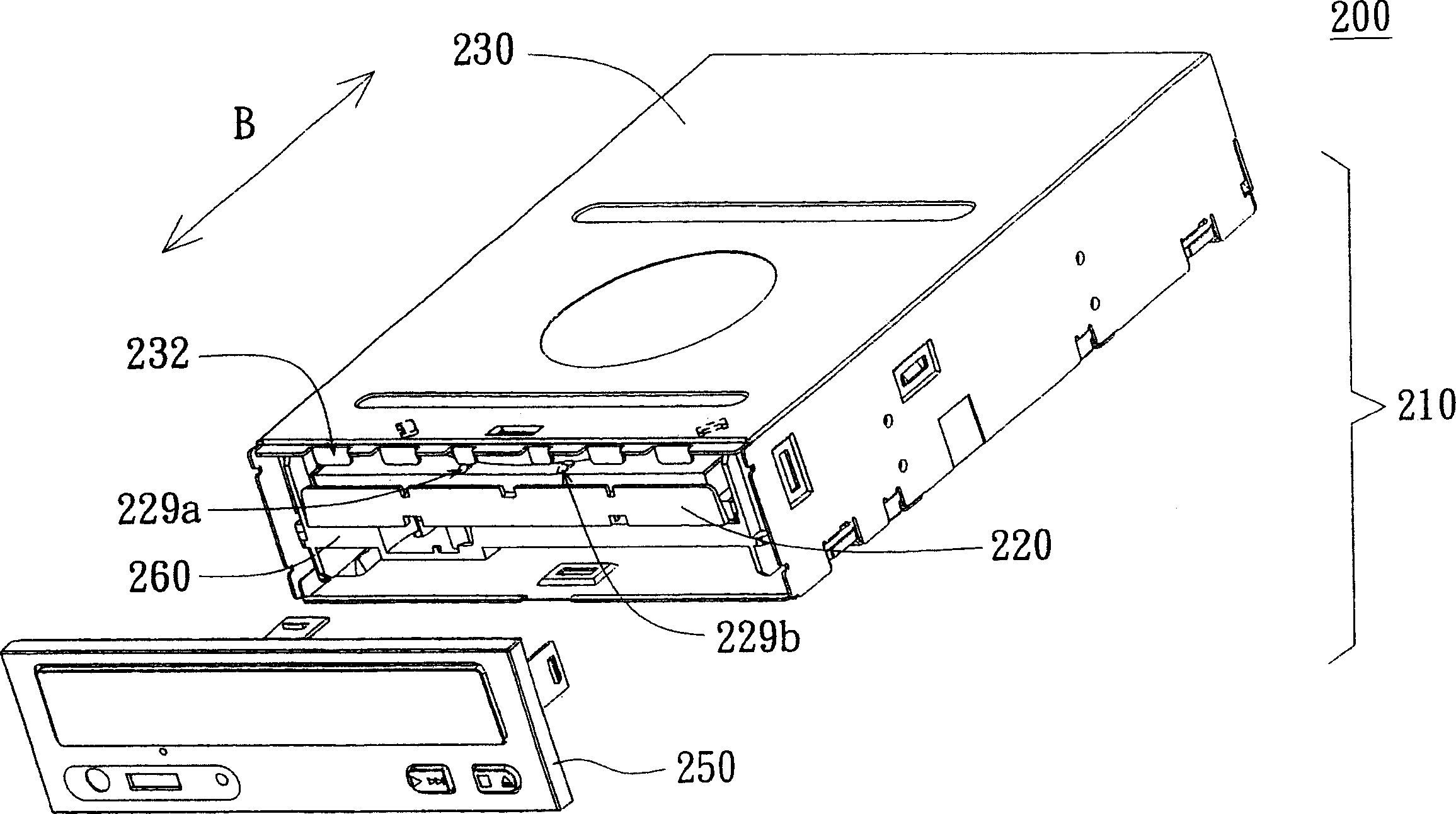
[0018] Please refer to figure 2 , which is a schematic diagram of a tray-type optical drive in a preferred embodiment of the present invention. The tray type optical drive 200 includes an optical drive body 210 , a tray 220 , an upper cover 230 , a panel 250 and a base 260 . The upper cover 230 is used to cover the optical drive body 210 , and the forming board 250 is disposed on the front side of the optical drive body 210 . The tray 220 is set on the optical drive body 210, and along the figure 2 In the way of moving in direction B shown in , the loaded disk enters the optical drive body 210 from the outside.

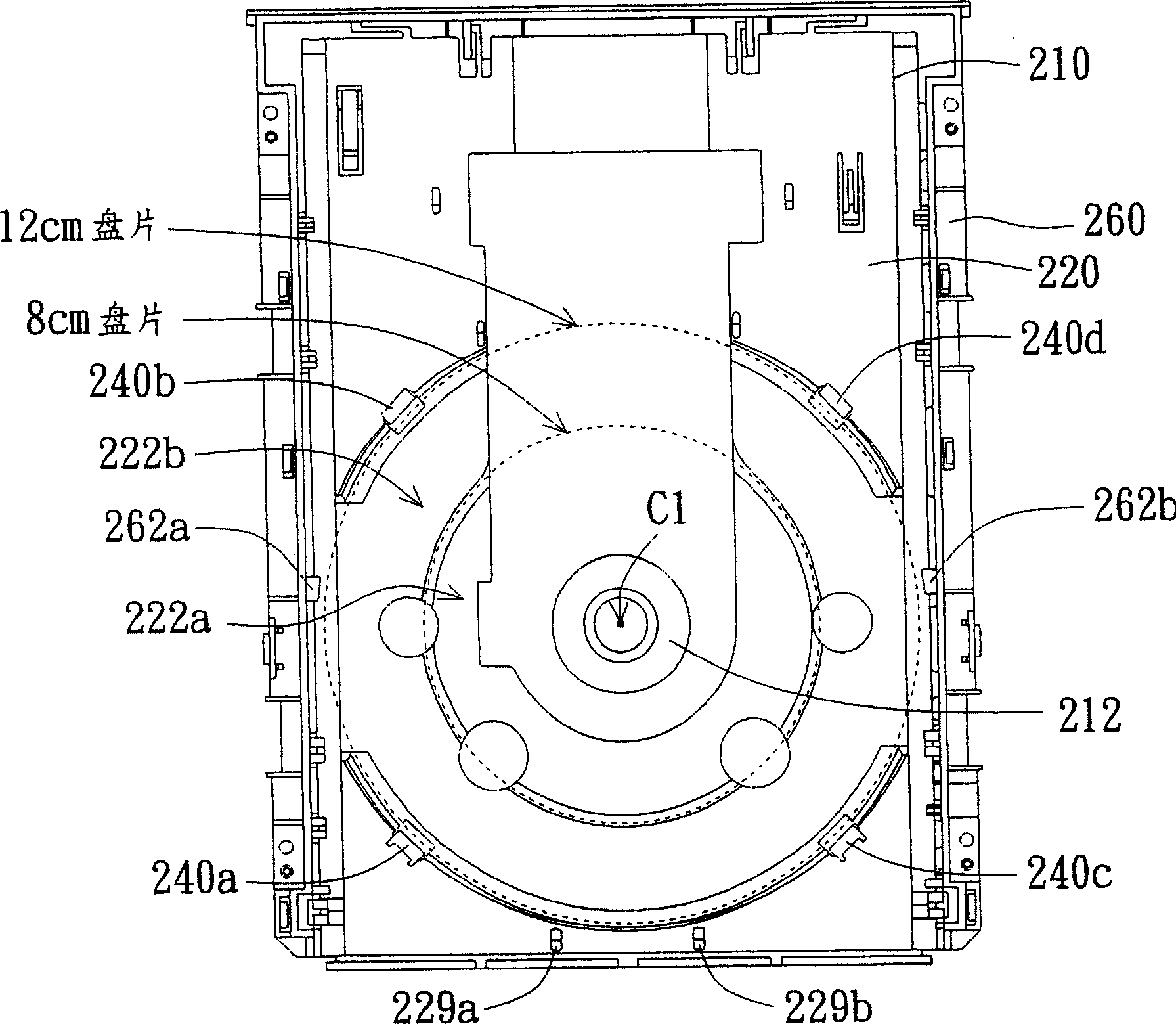
[0019] Please refer to Figure 3A , which shows a schematic view of the tray 220 , the optical drive body 210 and the base 260 . The optical drive body 210 is disposed in the base 260 , and in this figure, the tray 220 has been moved into the optical drive body 210 . Two sides of the base 260 are respectively provided with protrusions 262a, 262b. The tray 220 ha...


PUM


Abstract

A tray CD-ROM drive comprises base, drive body set inside base, panel set front of drive body, and drive tray set on drive body by way of accessing drive body. The tray comprises at least a holder and a groove to put disk with horizontal bearing zone, inclined surface zone and vertical bearing zone, the latter two zones are connected and on outside of horizontal bearing zone; when lay horizontal, the edge of disk touches the horizontal bearing zone; when lay vertical, the holder set on disk groove is against the edge of disk to locate the disk, both the vertical bearing zone and holder are against the lower margin, and the top margin leans horizontally the horizontal bearing zone.

Description

technical field [0001] The invention relates to a tray-type optical drive, in particular to a tray-type optical drive which improves the reliability of vertical placement of discs. Background technique [0002] In today's information explosion, most multimedia products are distributed in the form of CDs. And due to the popularity of consumer CDs, almost every computer includes a CD drive. At present, when the common tray-type optical drives on the market are installed on ordinary computers, most of them are set in such a way that the disk plane is horizontal. This type of tray-type optical drives is called a horizontal optical drive, which can meet the requirements of desktop computers It can be used in vertical hosts, or applied to external optical drives. In the same way, when the disk plane is set in a vertical state, it is called a vertical optical drive, which can be used as a platform host of a desktop computer, or applied to an external optical drive to make better ...

Claims


Application Information

Patent Timeline
Patent Type & Authority Applications(China)
IPC IPC(8): G11B17/03
Inventor 吴仁琛彭文宽
Owner QUANTA STORAGE INC
Learn More