Dimmer for cold cathode fluorescent tube

A technology of a cold cathode fluorescent lamp and a dimming device, which is applied in the field of brightness devices, can solve the problems of a sudden drop in the output voltage, affecting the service life and the like

Inactive Publication Date: 2005-11-02
ZIPPY TECH
View PDF1 Cites 4 Cited by
  • Summary
  • Abstract
  • Description
  • Claims
  • Application Information

AI Technical Summary

Problems solved by technology

This technology has two obvious defects, that is, the low-frequency interference will resonate with the shielding period, and the sudden change of the load will also cause a sudden drop in the output voltage; especially using this power control mode to drive the piezoelectric transformer will make the voltage Electric transformers frequently operate repeatedly under the condition of being charged or completely cut off the power supply, which will affect the service life of piezoelectric transformers

Method used


Image

  • Dimmer for cold cathode fluorescent tube
  • Dimmer for cold cathode fluorescent tube
  • Dimmer for cold cathode fluorescent tube

Examples


Embodiment Construction

[0020] The preferred embodiments and detailed technical contents of the present invention are described in detail below in conjunction with the accompanying drawings.

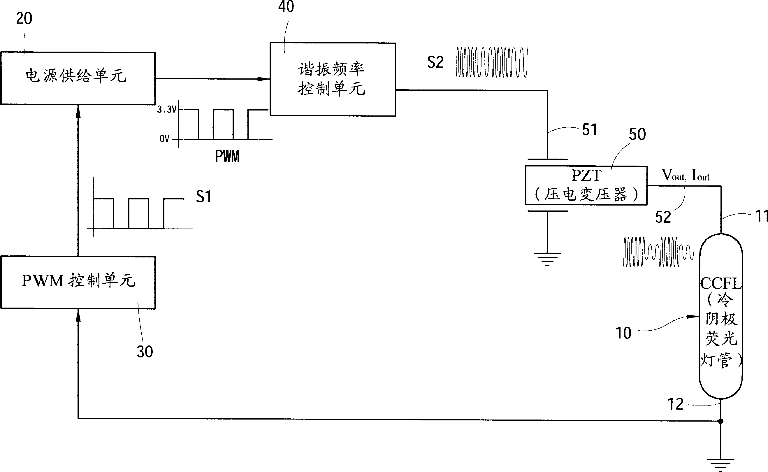
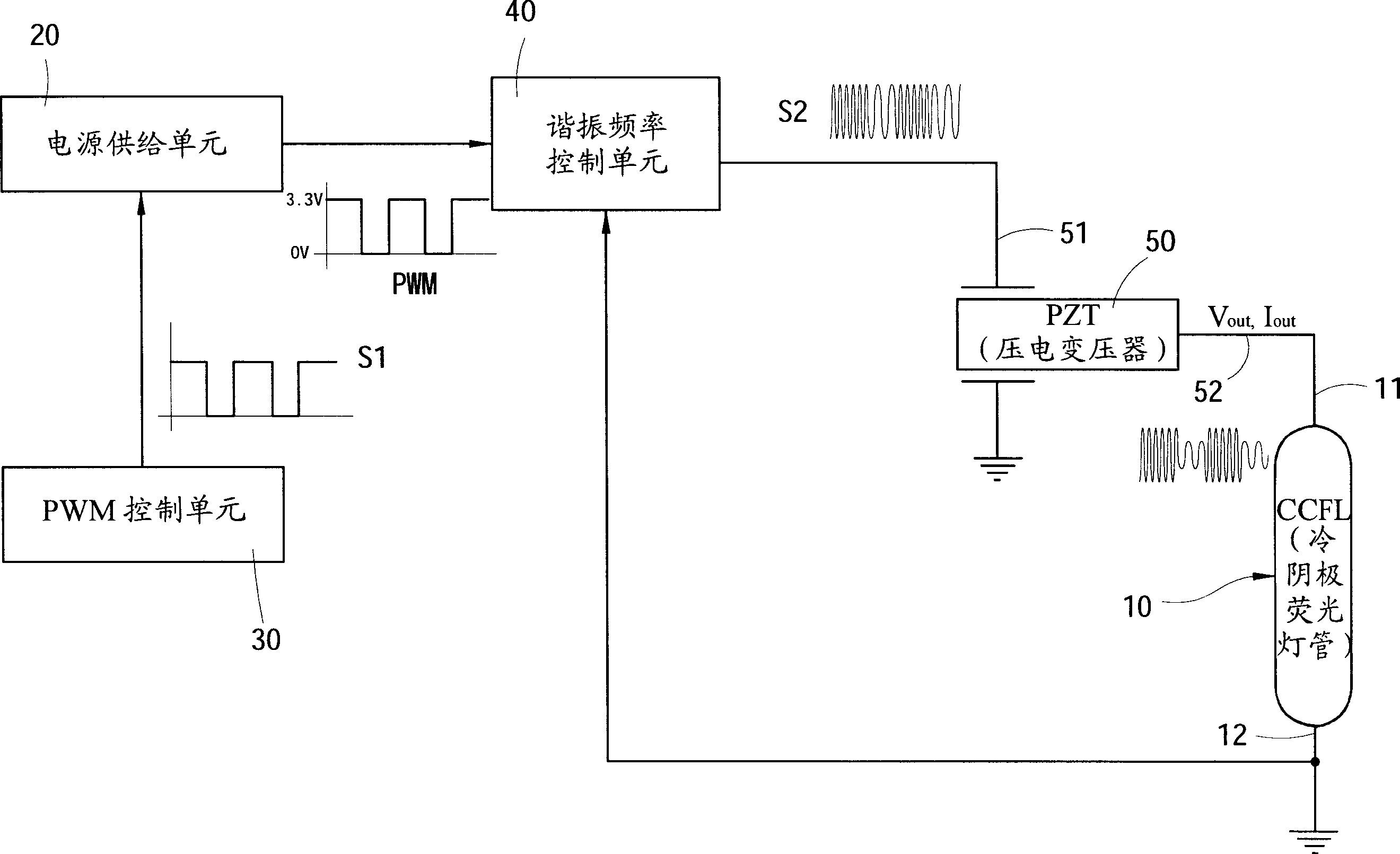
[0021] First, see figure 1 , which is the first preferred embodiment of the present invention, it can be understood from the circuit structure in the figure that the dimming device applied to the CCFL tube 10 includes:

[0022] A power supply unit 20, used to provide the DC power required to drive the CCFL tube 10 (depending on the specifications of the CCFL tube 10, generally a DC power supply with a voltage of 0 volts to several volts);

[0023] A PWM control unit 30 outputs a pulse signal S1 with pulse width modulation technology, and uses the pulse signal S1 to control the power supply unit 20 to output a pulse signal with a duty cycle T on and T off The pulse width modulation control signal, in short, is to use the pulse signal S1 to change the duty cycle of the direct current (DC) output by the power su...


PUM


Abstract

The invention discloses a light modulation apparatus for cold cathode fluorescent lamp tube, and discloses an apparatus which combines with frequency conversion and impulse width change, it adjust the brightness of the cold cathode fluorescent lamp tube through changing the output current and voltage of the piezo-electric transformer; the invention uses a PWM controller to adjust work periodic time, and uses a frequency to control the IC to work in different work periodic time, so to drive the resonant frequency of the piezo-electric transformer, by this to adjust the output current and voltage of the piezo-electric transformer, and then provides a light modulation apparatus which can adjust the brightness of the cold cathode fluorescent lamp tube and improve the age limit of the piezo-electric transformer.

Description

technical field [0001] The invention relates to a dimming device for a fluorescent lamp, in particular to a device for adjusting the brightness of a cold-cathode fluorescent lamp by changing the driving mode of a piezoelectric transformer and then changing its output voltage and current. Background technique [0002] The ceramic piezoelectric transformer was first proposed by C.A. Rosen in 1956. Its working principle is different from that of magnetic transformers that convert electromagnetic energy. Piezoelectric transformers first convert electromotive force into mechanical energy (this conversion process is called inverse piezoelectric effect), and then convert mechanical energy into electrical energy (this conversion process is called positive piezoelectric effect). effect). [0003] Because of the development of magnetic transformers and piezoelectric transformers, we can manufacture high-efficiency, small-size converters. Magnetic transformers may be thicker, heavier...

Claims


Application Information

Patent Timeline
Patent Type & Authority Applications(China)
IPC IPC(8): H05B41/38
Inventor 周进文郑英男吴光明钟金标
Owner ZIPPY TECH
Why Eureka
Try Eureka