Anchoring means for the sheath of a bowden cable

An anchoring device and collar technology, applied in the direction of flexible shaft, transportation and packaging, shaft, etc., can solve the problems of difficult and time-consuming assembly, etc.

Inactive Publication Date: 2005-11-02
HI LEX CABLE SYST
View PDF0 Cites 17 Cited by
  • Summary
  • Abstract
  • Description
  • Claims
  • Application Information

AI Technical Summary

Problems solved by technology

Furthermore, many conventional bracket arrangements tend to have somewhat complex structures that are relatively difficult and time consuming to assemble

Method used


Image

  • Anchoring means for the sheath of a bowden cable
  • Anchoring means for the sheath of a bowden cable
  • Anchoring means for the sheath of a bowden cable

Examples


Embodiment Construction

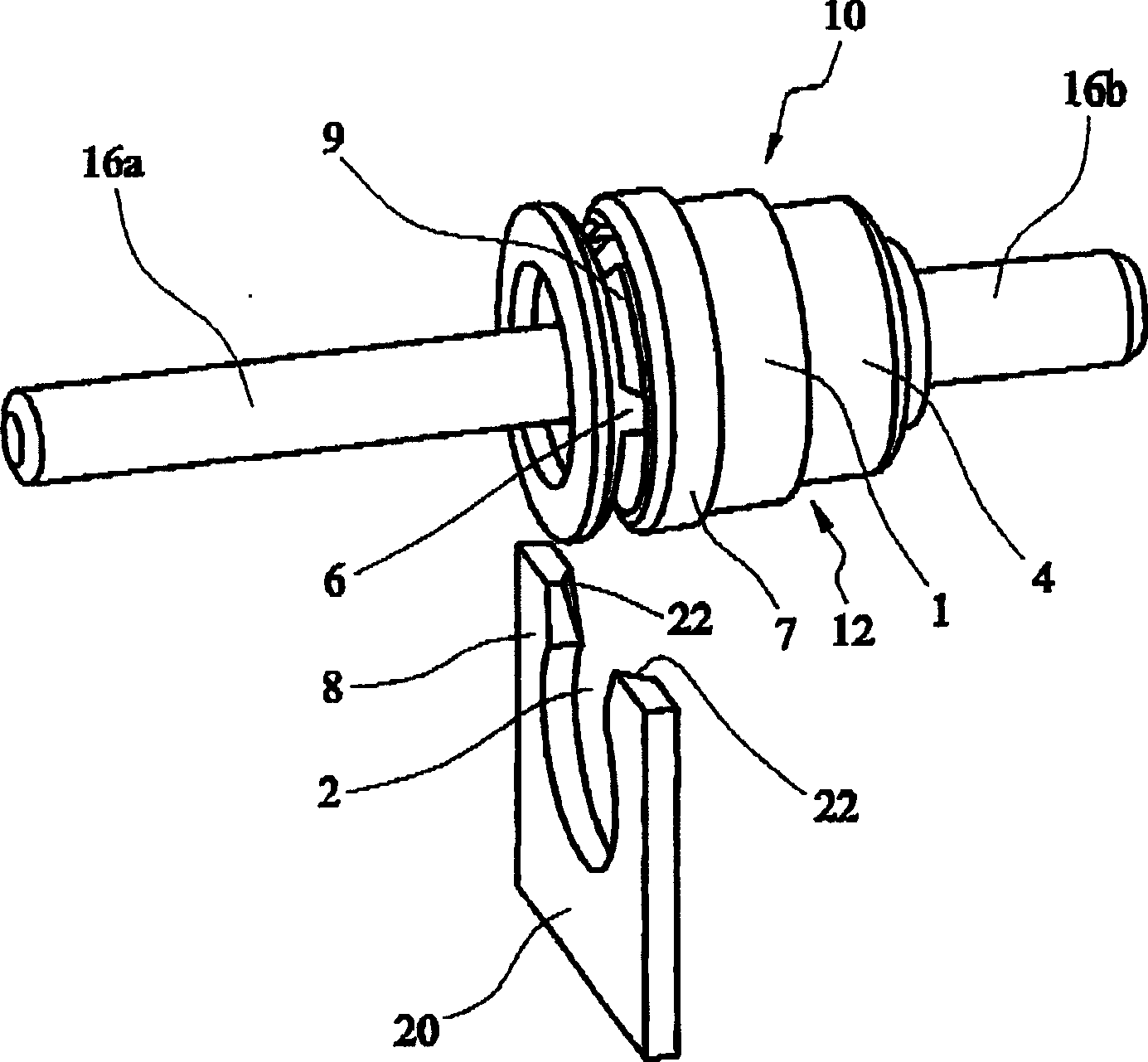
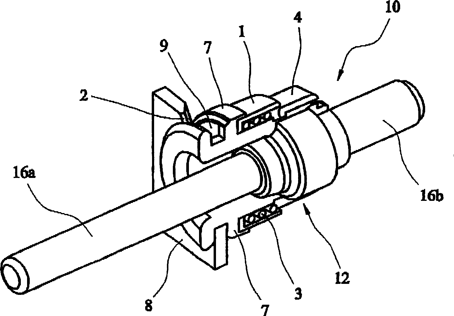
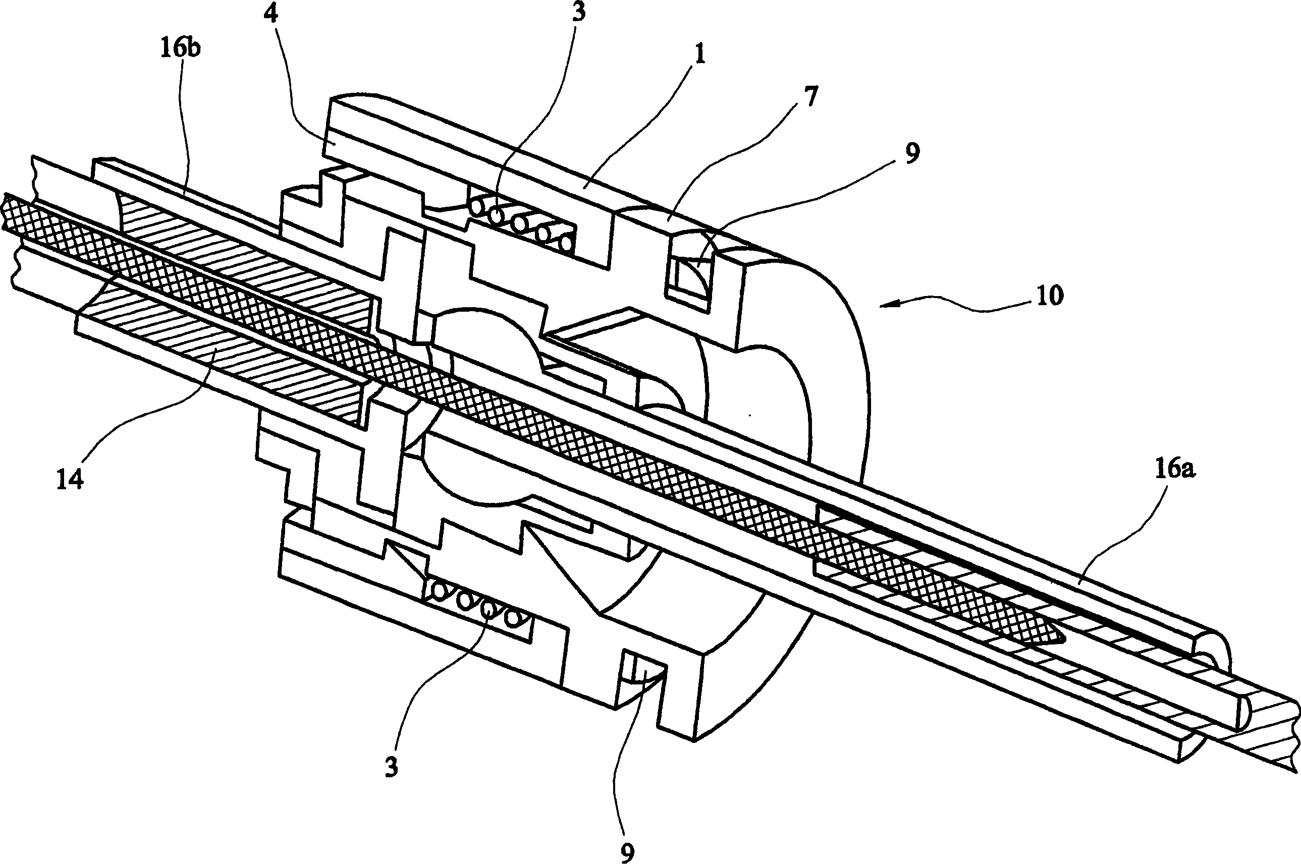
[0019] Please refer to the attached Figures 1 to 3 , a support for an elongated member anchoring a sheath such as a flexible cable (also called a push-pull cable) is generally indicated at 10 . Specifically, stent 10 includes a generally cylindrical body 12 having an axial through cavity 14 along which a sliding core (not shown) of a push-pull cable is generally disposed.

[0020] Extending at opposite ends of the body 12 are two cylindrical tubular portions 16a, 16b of smaller diameter than the body 12 . The portion 16a guides the core cord and the end rod (the end bar prevents the core cord from bending between the fixed point for the outer cord (immovable) and the anchor point for the inner cord (movable)) from sliding. Portion 16a is used to secure the outer cable to main body 12 .

[0021] The main body 12 comprises a carrier ring 7 defining two opposing shoulders 7 a , 7 b the axial distance between which is fixed and which define the junction of the stent body 12 . ...


PUM


Abstract

An anchoring device ( 10 ) for anchoring an elongate member to a fixed member ( 8 ), having a slot ( 20 ) leading to an edge thereof, the anchoring device comprising a sleeve ( 7 ) which is fixable coaxially around said elongate member and which is provided with a circumferential groove the axial length of which is sufficient to accommodate the thickness of the fixed member ( 8 ) at said slot ( 20 ), the outer diameter of the groove being less than the inner diameter of the slot ( 20 ), the anchoring device ( 10 ) further comprising a collar member ( 1 ) which is carried by, and axially moveable along, said sleeve, said collar member ( 1 ) having a leading edge ( 9 ) which extends into said groove when the anchoring device is located within said slot ( 20 ), to effectively increase the diameter of said groove and prevent said anchoring device from being withdrawn from said slot, the collar member ( 1 ) being arranged such that the leading edge ( 9 ) thereof can be withdrawn from the groove by moving the collar member along the sleeve in an axial direction away from the slot, so as to enable the anchoring device to be withdrawn from the slot.

Description

technical field [0001] The present invention relates to a device for anchoring an elongate member to another member, and in particular, but not exclusively, to a mount for anchoring a flexible control cable to a fixed member of the chassis or body of a vehicle. Background technique [0002] A push-pull cable is a device used to convert a push / pull motion at one location to a push / pull motion at a different location (in the same direction or in any different direction), often for control purposes, and such cables include control wires A flexible conduit within which to slide to perform a desired function. In order for the relative movement of the control wire and conduit to occur in a controlled manner for reliable operation of, for example, a clutch or gearbox mechanism or throttle of a motor vehicle, each end of the conduit needs to be anchored, eg to the body of the vehicle. In particular the custom has been developed to anchor the ends of the conduits to openings in brac...

Claims


Application Information

Patent Timeline
Patent Type & Authority Applications(China)
IPC IPC(8): F16C1/26
CPCF16C2326/01F16C1/105F16C1/265Y10T403/71Y10T74/2045Y10T74/20462F16C2326/20
Inventor 格雷厄姆·福斯特亚当·理查兹
Owner HI LEX CABLE SYST
Why Eureka
Try Eureka