Safety drawn-back and self-broken type syringe

A syringe and self-destruct technology, applied in the field of medical devices, can solve problems such as hard-to-reach blockage, high cost, and failure to use normally

Inactive Publication Date: 2005-11-09
陈嘉农
View PDF1 Cites 0 Cited by
  • Summary
  • Abstract
  • Description
  • Claims
  • Application Information

AI Technical Summary

Problems solved by technology

The process of making the plug and piston of the above-mentioned syringe integrated is relatively difficult, the production yield is low, and the cost is high. When in use, due to the good elasticity of the rubber, the cut at the rear end of the plug is not easy to break, and it is difficult to achieve the plugging effect. ; If it is bonded, it is difficult to accurately locate the plug at the center of the piston, because the bonding area is small, so it is easy to fall off when not in use, and cannot be used normally

Method used


Image

  • Safety drawn-back and self-broken type syringe
  • Safety drawn-back and self-broken type syringe
  • Safety drawn-back and self-broken type syringe

Examples


Embodiment 1

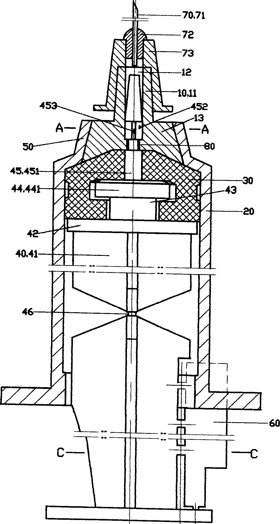
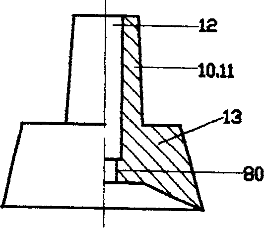
[0041] See figure 1Referring to Fig. 7, the materials used in the syringe of this embodiment meet the national standard. The syringe of the present embodiment comprises an outer jacket 20, a piston 30 and a core rod 40; the core rod 40 is an integral part having a shaft 41, a shaft top sheet 42, a neck 43 and a head 44; the piston 30 is sleeved on the core rod 40 On the head 44 of the syringe, the syringe also has a retractable part 10. The retractable part 10 is an integral part with a cone head 11 and a positioning part 13. The positioning part 13 is arranged on the lower part of the retractable part 10. The retractable part 10 has an axial through hole 12; an airtight positioning part 50 is provided on the upper part of the overcoat 20, the overcoat 20 and the airtight positioning part 50 are integrated, and the airtight positioning part 50 has a through hole 51; the cone head 11 of the retractable part 10 is worn Out of the through hole 51 of the airtight positioning part...

Embodiment 2

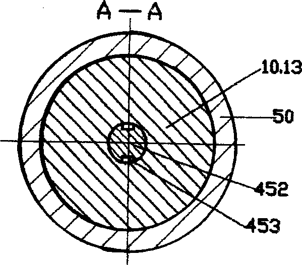
[0044] See Fig. 8 to Fig. 11, the needle tube 71 of the syringe of this embodiment is fixed on the retractable part 10 through the connection part 72 and the inner wall of the axial through hole 12 of the retractable part 10; see Fig. 9 and Fig. 10 , the lower end of the inner wall of the through hole 51 of the airtight positioning part 50 on the top of the outer cover 20 is provided with a closed step 52, then a step 14 is provided at the lower end of the positioning part 13 of the retractable part 10; the positioning of the retractable part 10 The outer diameter of the step 14 of the part 13 is greater than the inner diameter of the airtight step 52 on the inner wall of the through hole 51 of the airtight positioning part 50 by 0.25mm, so as to achieve the purpose of strengthening and ensuring that the syringe can normally absorb and inject medicinal liquid; the retractable part 10 The outer wall of the positioning part 13 has a taper that is small at the top and large at the...

Embodiment 3

[0046] 12 to 14, the syringe of this embodiment is provided with a closed step 52 at the upper end of the inner wall of the through hole 51 of the airtight positioning part 50 on the upper part of the overcoat 20, and then at the upper end of the positioning part 13 of the retractable part 10. Step 14; the outer diameter of the step 14 of the positioning part 13 of the retractable part 10 is greater than the inner diameter of the airtight step 52 on the inner wall of the through hole 51 of the airtight positioning part 50. 0.2mm; see Figure 12 and Figure 13, in the retractable An O-ring 131 is provided on the outer wall of the positioning portion 13 of the component 10, and a sealing ring positioning portion 132 is provided on the outer wall of the positioning portion 13 of the retractable component 10, and the O-ring 131 is sleeved and fixed on the sealing ring. On the positioning part 132; the outer wall of the O-ring 131 can be matched with the inner wall of the through hole...


PUM


Abstract

A high-safety self-destroyed injection is composed of an external pipe with a sealed locator having a through hole, a core rod consisting of main rod, top plate, neck and head, a piston arranged on the head of core rod, and a withdrawable unit with a conic head inserted through the through hole of said sealed locator of external pipe, and a locator whose external surface is closely matched with the inner surface of the through hole of said sealed locator.

Description

technical field [0001] The invention relates to a safe self-destruction syringe, which belongs to the field of medical instruments. Background technique [0002] Chinese patent No. is 00219356.6, and the utility model patent description entitled "Blocking Type Disposable Syringe" discloses a syringe. The syringe includes a jacket, a core rod, and a piston; the jacket has a cone head, the cone head is provided with a cone head hole, and an annular boss is arranged in the cone head hole; the front end of the piston is provided with a plug, and the rear end of the plug has a cutout. There is a core bone in the center; the piston is connected with the plug, which can be made in one piece or bonded; the plug has a taper, and the front end is a small head; the inner wall of the annular boss is provided with at least one axial guide groove; A limit piece is provided at the rear of the rod. The process of making the plug and piston of the above-mentioned syringe integrated is rela...

Claims


Application Information

Patent Timeline
Patent Type & Authority Applications(China)
IPC IPC(8): A61M5/50
Inventor 陈嘉农邹志尚
Owner 陈嘉农
Why Eureka
Try Eureka