Hollow slab made from concrete reinforced by steel bar cast in-site

A reinforced concrete and hollow slab technology is applied in the field of cast-in-place reinforced concrete hollow slabs, which can solve the problems of easy generation of cracks, stress concentration, cracking and damage, etc., and achieve the effects of easy construction, elimination of stress concentration, and low cost.

Inactive Publication Date: 2005-11-16
湖南邱则有专利战略策划有限公司
View PDF3 Cites 0 Cited by
  • Summary
  • Abstract
  • Description
  • Claims
  • Application Information

AI Technical Summary

Problems solved by technology

But this kind of hollow slab is subjected to more complex force and concentrated stress at the corner of the cavity member, and is prone to cracks or even cracks and damage. Therefore, it is urgently needed to develop a new type of cast-in-place reinforced concrete hollow slab.

Method used


Image

  • Hollow slab made from concrete reinforced by steel bar cast in-site
  • Hollow slab made from concrete reinforced by steel bar cast in-site
  • Hollow slab made from concrete reinforced by steel bar cast in-site

Examples


Embodiment Construction

[0056] The present invention will be further described below in conjunction with the accompanying drawings and embodiments.

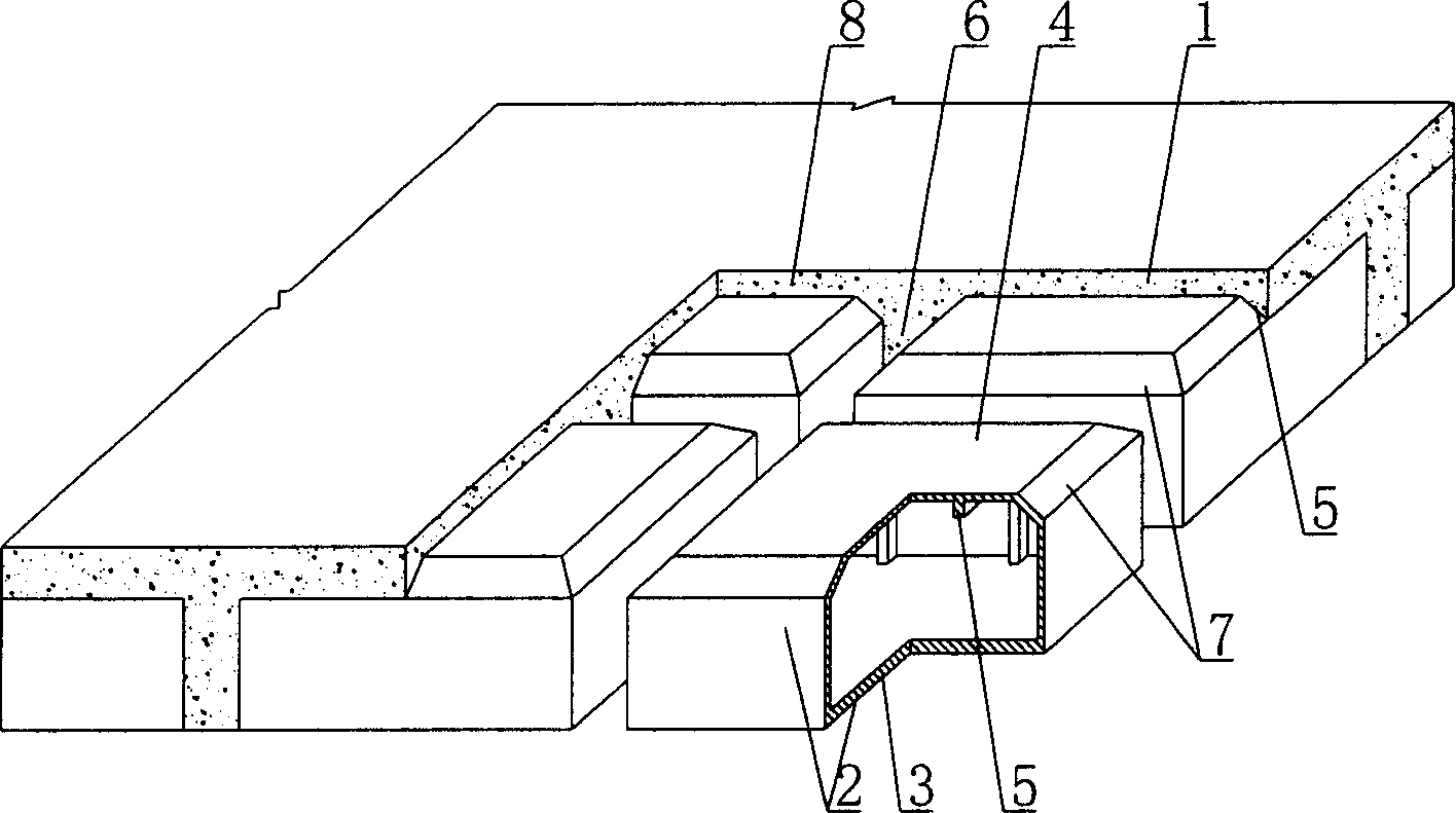
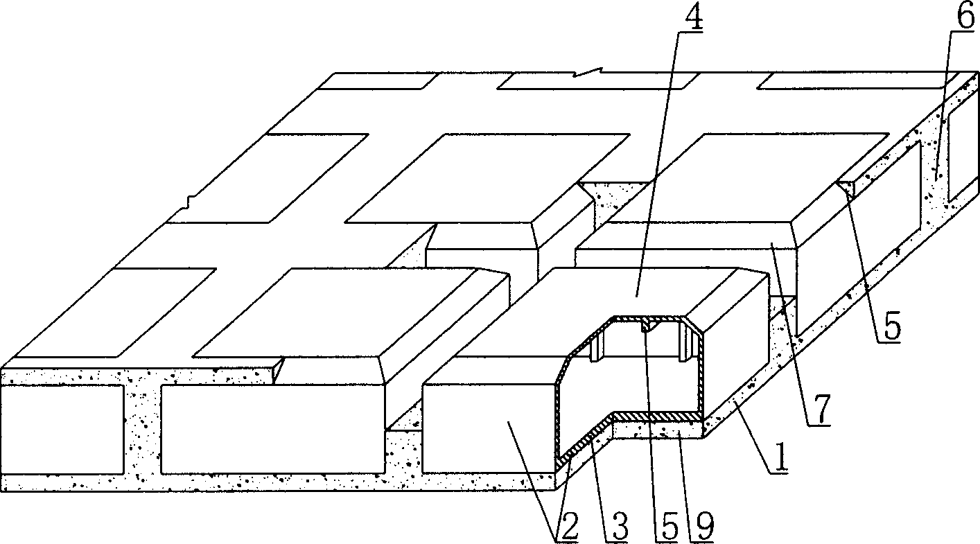
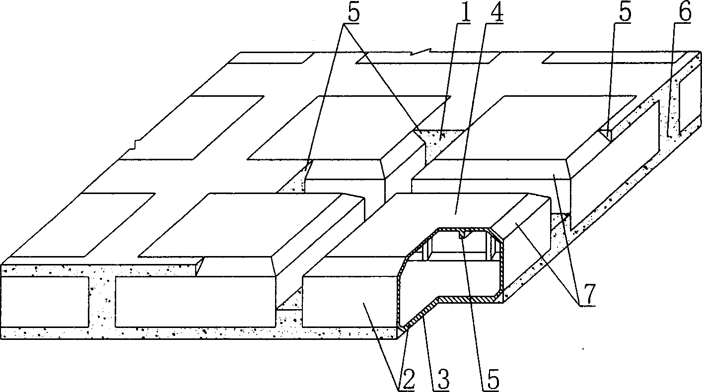
[0057] As shown in the accompanying drawings, the present invention includes a reinforced concrete 1 and a cavity member 2. The cavity member 2 is wrapped in the cast-in-place reinforced concrete 1. The cavity member 2 is formed by connecting a structural bottom plate 3 and a cavity formwork 4. The cavity template 4 is provided with at least one reinforcing rib 5, and the cavity components 2 are arranged alternately with cast-in-place concrete ribs 6. It is characterized in that at least one chamfer 7 is provided at the corner of the cavity component 2. The reinforcing rib 5 of the cast-in-place concrete is formed at the chamfer 7. figure 1 It is a structural schematic diagram of Embodiment 1 of the present invention. In the attached drawings, 1 is reinforced concrete, 2 is a cavity member, 3 is a structural floor, 4 is a cavity formwork, 5 is a reinfo...


PUM


Abstract

The present invention relates to a cast-in-situ reinforced concrete hollow slab, including reinforced concrete and hollow cavity members which are wrapped and contained in the cast-in-situ reinforced concrete. The hollow cavity member is made up by using structure bottom plate and hollow cavity form which are connected together, and on the hollow cavity form at least a reinforcing rib is set. The hollow cavity members are alternately arranged, between them the cast-in-situ concrete rib is formed respectively. It is characterized by that the turning corner position of said hollow cavity member is equipped with at least a chamfer in which the cast-in-situ concrete reinforcing rib is formed. Said invention is applicable to various cast-in-situ concrete foor, roof, wall body, foundation bedplate and structure of road and bridge engineering, specially applicable to hollow beamless floor.

Description

(1) Technical field [0001] The invention relates to a cast-in-place reinforced concrete hollow slab. (2) Background technology [0002] At present, the cast-in-place concrete hollow floor is a widely used floor structure, and the lightweight permanent tire mold filled in it includes hollow tubes and cavity formwork components. For example, the patent No. ZL99249798.1, which the applicant applied for on November 29, 1999, is a utility model patent named "fiber-reinforced thin-walled member for reinforced concrete filling", which discloses a thin-walled formwork member, including an upper plate, The surrounding side walls, the lower bottom plate, the upper plate, the surrounding side walls and the lower bottom plate form a polyhedron cavity. Another example is that the application number applied by the applicant on November 23, 2001 is 01140106.0, the publication number is CN1356442, and the name is called "a kind of cavity structure formwork for cast-in-place reinforced conc...

Claims


Application Information

Patent Timeline
IPC IPC(8): E04B5/36
Inventor 邱则有
Owner 湖南邱则有专利战略策划有限公司
Why Eureka
Try Eureka