Transmission canal with diphasic heat sink

A heat dissipation device and transmission flow technology, applied in indirect heat exchangers, lighting and heating equipment, cooling/ventilation/heating transformation, etc., can solve the problems of increasing the frictional resistance of liquid return, drying the evaporator, limiting heat dissipation capacity, etc.

Inactive Publication Date: 2005-11-16
王训忠
View PDF2 Cites 12 Cited by
  • Summary
  • Abstract
  • Description
  • Claims
  • Application Information

AI Technical Summary

Problems solved by technology

However, this design has disadvantages in that the condensed liquid must pass through the condenser, the liquid return channel and the long capillary structure in the evaporator in the process of returning to the evaporator.
Although the added capillary structure increases the capillar

Method used


Image

  • Transmission canal with diphasic heat sink
  • Transmission canal with diphasic heat sink
  • Transmission canal with diphasic heat sink

Examples


Embodiment Construction

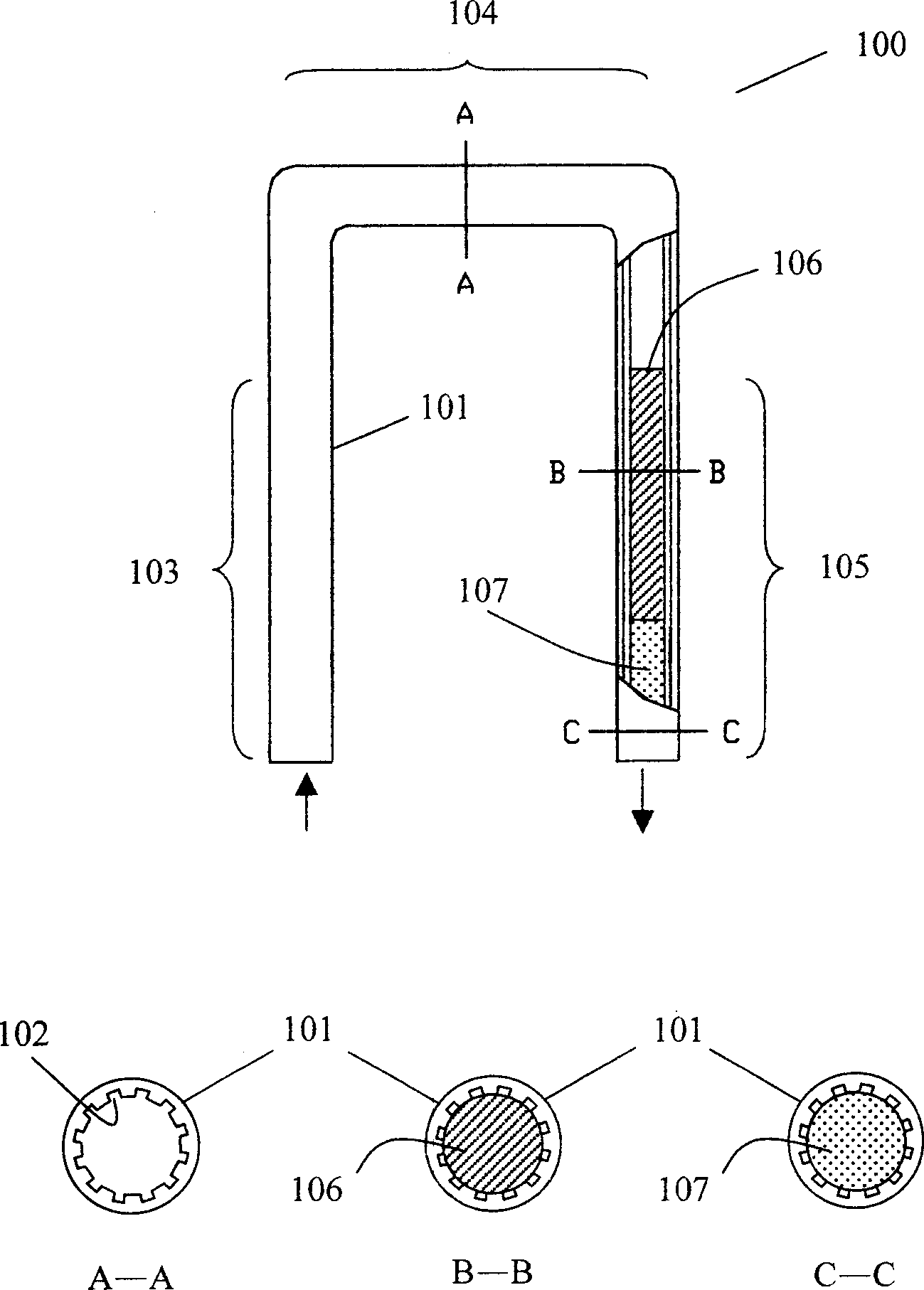
[0017] image 3 Disclosed is a cross-sectional view of a first embodiment of a transmission channel suitable for a two-phase heat dissipation device proposed by the present invention. The transmission channel 100 is divided into three sections: a steam channel 103 , a condensation channel 104 , and a liquid return channel 105 . On the inner wall of the metal tube 101, there is a ring groove micro-flow channel 102, which can be made on the tube wall when the tube is extruded and formed. A microchannel is defined herein as a long fluid channel with a hydraulic diameter of less than 500 μm, and its cross-sectional shape can be V-shaped, triangular, square, trapezoidal, wavy or other shapes. A plug 106 is used to plug the tube core area of ​​the liquid return flow channel 105 to form a ring of closed micro channel arrays. The above-mentioned plug 106 can be made of metal, plastic, or other heat-resistant materials. The bottom corners of the grooved micro-channel (as shown in se...


PUM


Abstract

Microchannels of groove are adopted in the invention to enhance capillarity of transmission channels of heat sink in two phases such as loop heat pipe, or capillary pumped loop or spray cooling device etc. Micro channels of groove can increase capillary force without increasing frictional resistance obviously so as to raise radiating efficiency. If effective sectional area of backflow channel is far smaller than sectional area of pipe in condensation segment, the capillarity actuating force of circular working fluid will be raised further. The said purpose can be done by using a plug to stop up core area of pipe in backflow segment or through treatment of shrinkage pipe.

Description

technical field [0001] The invention relates to the heat dissipation of heat sources with high heat flux, and can be used for heat dissipation of electronic chips in computers or objects to be cooled in other applications. More particularly, it relates to transport lines in loop heat pipes, capillary pumped loops, spray cooling devices, or other two-phase cooling devices. Background technique [0002] With the continuous development of electronic technology, stronger functions can be completed on chips with smaller areas or volumes, but at the same time, it is accompanied by higher heat generation. In order to maintain the chip at a permissible temperature to prevent its performance from being reduced or damaged, High-efficiency heat dissipation is required. [0003] The two-phase heat dissipation method is a simple but extremely effective heat dissipation method, which has been widely used in various heat dissipation needs. Its working principle is to transfer heat by the...

Claims


Application Information

Patent Timeline
IPC IPC(8): H01L23/427
Inventor 王训忠
Owner 王训忠
Why Eureka
Try Eureka