Gravity-assisted loop heat pipe with ultrasonic vibration atomizing device

A technology of atomization device and ultrasonic vibration, which is used in circuits, indirect heat exchangers, lighting and heating equipment, etc., can solve the problems of lack of liquid working medium, low critical heat flux density, affecting heat exchange performance, etc., and achieve heat exchange performance. The effect of improving the heat flux density of the critical heat exchange, avoiding the contact thermal resistance, and reducing the hysteresis

Inactive Publication Date: 2012-06-20
ZHEJIANG COLLEGE OF CONSTR
View PDF7 Cites 13 Cited by
  • Summary
  • Abstract
  • Description
  • Claims
  • Application Information

AI Technical Summary

Problems solved by technology

[0005] (1) The traditional gravity-assisted circuit heat pipe directly sticks the chip on the outer surface of the evaporation chamber, so there is inevitably a contact thermal resistance between the tube wall of the evaporation section and the chip, and the diffusion heat of the heat from the contact part to the entire evaporation chamber resistance;
[0006] (2) The evaporation cavity of the traditional gravity-assisted circuit heat pipe is similar to the state of pool boiling. The chip heat is transferred to the liquid working medium in the evaporation cavity through the evaporation cavity wall. The degree of superheat required for heat transfer increases with the increase of heat flux, and the critical heat flux is relatively low
Its main disadvantage is that the superheated gas will gather at the top of the cavity due to the buoyancy, and wrap the heat source on the back of the

Method used


Image

  • Gravity-assisted loop heat pipe with ultrasonic vibration atomizing device
  • Gravity-assisted loop heat pipe with ultrasonic vibration atomizing device
  • Gravity-assisted loop heat pipe with ultrasonic vibration atomizing device

Examples


Embodiment Construction

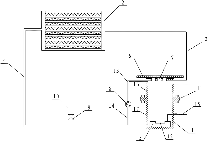
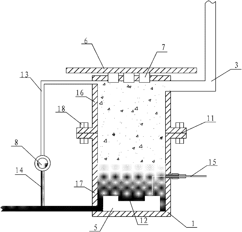
[0033] like figure 1 and figure 2 As shown, a gravity-assisted loop heat pipe with an ultrasonic vibration atomization device includes an evaporation chamber 1, a condensation section 2, and a gas phase tube 3 connecting the working medium outlet of the evaporation chamber 1 and the working medium inlet of the condensation section 2, and the condensation section The working medium outlet of 2 is connected with the working medium inlet of evaporation chamber 1 through a liquid phase tube 4; an ultrasonic vibration atomization device 5 is installed at the bottom of the inner cavity of evaporation chamber 1, and an atomization sheet is installed on the upper surface of the ultrasonic vibration atomization device 5 12. There are a number of notches corresponding to the position and shape of the cooled chip 7 on the top wall of the evaporation chamber 1. After being packaged by the cooled chip 7, one end surface is fixed on the silicon substrate 9, and the other end surface passes...


PUM


Abstract

The invention discloses a gravity-assisted loop heat pipe with an ultrasonic vibration atomizing device, which comprises an evaporating cavity, a condensing section, a gas-phase pipe and a liquid-phase pipe. The evaporating cavity and the condensing section are communicated closely to form a circulating loop by the gas-phase pipe and the liquid-phase pipe, the condensing section is arranged above the evaporating cavity, the ultrasonic vibration atomizing device is arranged at the bottom of an inner cavity of the evaporating cavity, and a plurality of slots communicated with the outside are arranged on the top surface of the evaporating cavity. A substrate is arranged above the evaporating cavity, a plurality of cooled chips are fixed on the bottom surface of the substrate, bottom surfaces of the cooled chips penetrate through the corresponding slots on the evaporating cavity, and four sides of each of the cooled chips are respectively connected with each of the slots hermetically. The gravity-assisted loop heat pipe with the ultrasonic vibration atomizing device adopts the mature technology, and the structure of the evaporating cavity can be changed flexibly according to the shapes of the cooled chips and the arrangement position of the substrate, so that the gravity-assisted loop heat pipe can be adaptable to cooling of chip arrays better, particularly has wider application prospect to cooling and heat control of ground high-heat-flux power-consumption electronic chip arrays, such as high-end CPUs (central processing units), high-power LED lamps, communication equipment and the like, and is high in practicability.

Description

technical field [0001] The invention belongs to the field of heat transfer element preparation, in particular to a gravity-assisted loop heat pipe with an ultrasonic vibration atomization device. Background technique [0002] On the one hand, for forty years, people have continuously improved the performance of electronic devices and reduced the cost of electronic devices by scaling down the size of MOSFETs (metal-oxide-semiconductor-field-effect transistors). At present, silicon integrated circuit technology driven by the proportional reduction of CMOS devices has entered the nanometer scale, and will continue to pursue the pursuit of Moore's Law, and further reduce the size of devices to meet the needs of chip miniaturization, high density, high speed and system Integration requirements. For example, Intel basically changes its process every two years and launched its first 45nm Penryn processor in 2007. The Penryn dual-core version has 410 million transistors built-in, ...

Claims


Application Information

Patent Timeline
IPC IPC(8): F28D15/02H01L23/427
CPCF28D15/0266H01L2924/0002H01L2924/00
Inventor 乔晓刚闵旭伟方民韩晓红
Owner ZHEJIANG COLLEGE OF CONSTR
Why Eureka
Try Eureka