Electronic device, loop heat pipe and cooling device

a technology of loop heat pipe and cooling device, which is applied in the direction of lighting, heating apparatus, electrical apparatus casing/cabinet/drawer, etc., can solve the problems of high production cost and insufficient cooling of a plurality of heat generating parts of conventional heat pipes

Inactive Publication Date: 2010-06-15
TOSHIBA CLIENT SOLUTIONS CO LTD
View PDF17 Cites 12 Cited by
  • Summary
  • Abstract
  • Description
  • Claims
  • Application Information

AI Technical Summary

Problems solved by technology

However, due to the fact that the above-described conventional loop-type heat pipe has a loop shape, it is necessary to form a through hole in a central portion of the container, and the formation of such a hole results in a high production cost, which is a problem.
Further, although the conventional type heat pipe is able to cool down a plurality of heat generating parts, it entails the following drawback.
For this reason, the conventional heat pipe is not adequate for cooling down a plurality of heat generating parts.

Method used


Image

  • Electronic device, loop heat pipe and cooling device
  • Electronic device, loop heat pipe and cooling device
  • Electronic device, loop heat pipe and cooling device

Examples


first embodiment

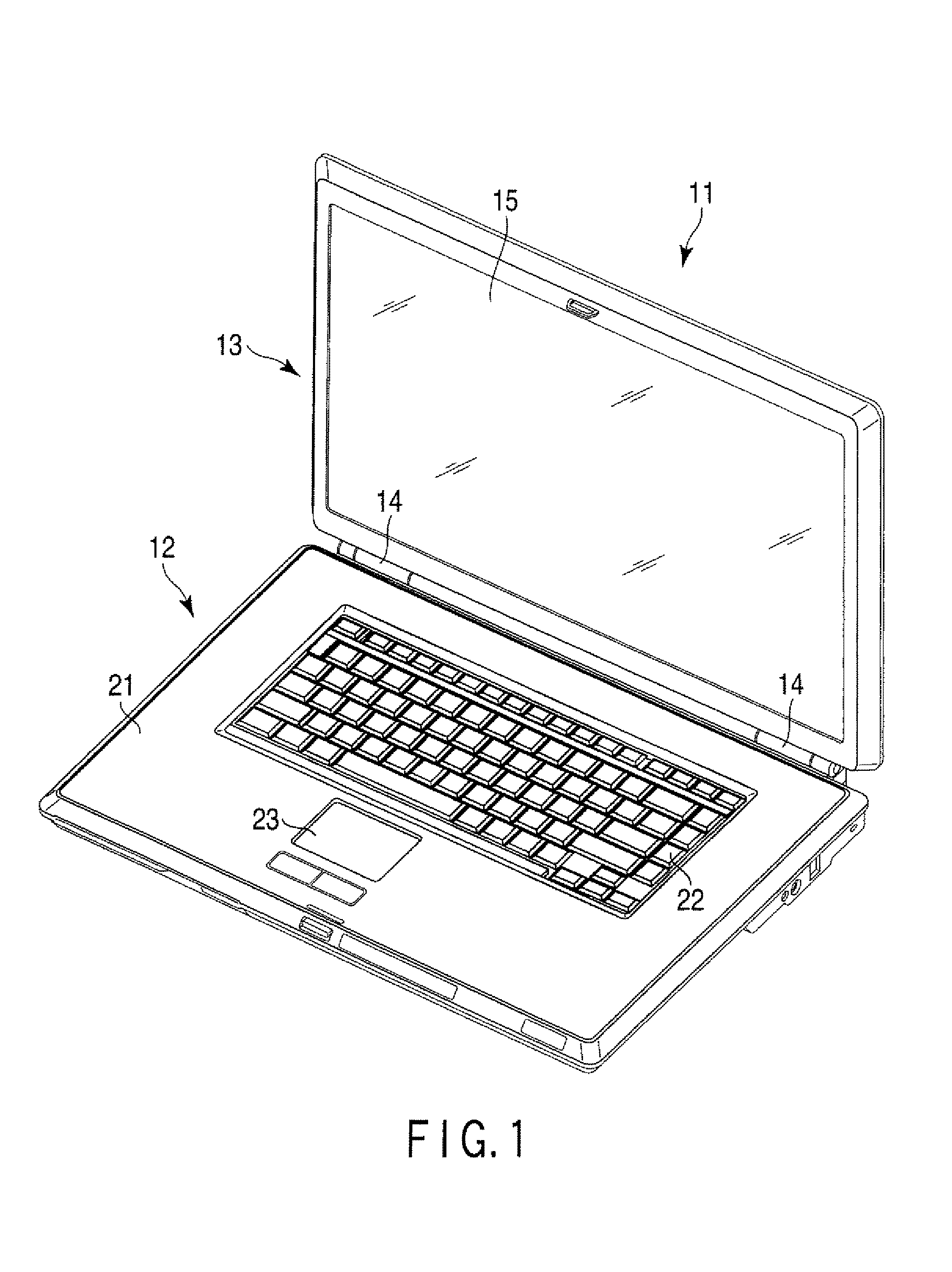
[0016]the electronic device will now be described with reference to FIGS. 1 to 5. As shown in FIG. 1, a portable computer 11, which is an example of the electronic device, includes a main body unit 12, a display unit 13 and a hinge mechanism 14 provided between the main body unit 12 and the display unit 13. The hinge mechanism 14 supports the display unit 13 so as to be pivotable with respect to the main body unit 12.

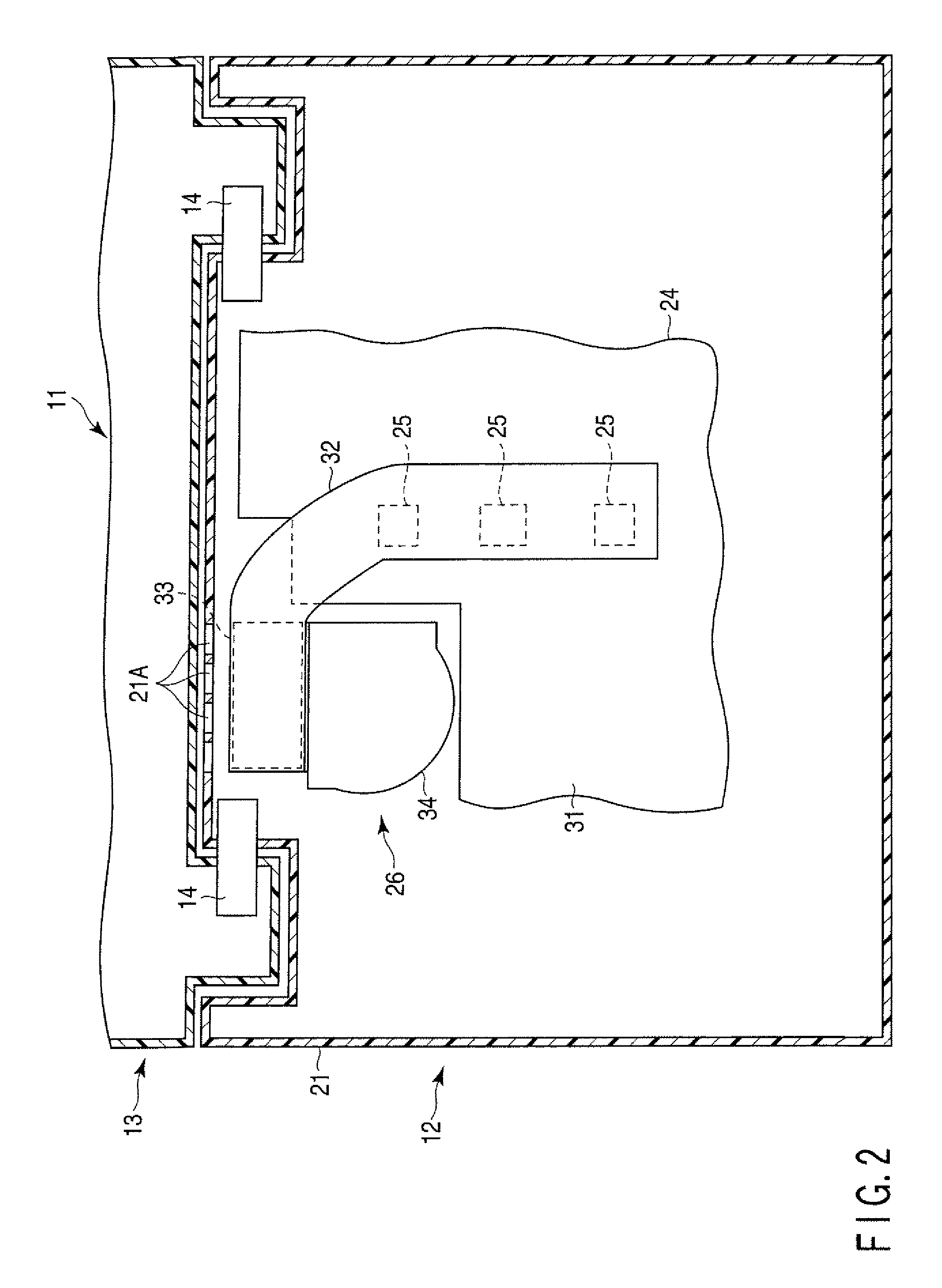
[0017]The display unit 13 includes a display 15. The display 15 is, for example, a liquid crystal display. As can be seen in FIGS. 1 and 2, the main body unit 12 contains a cabinet 21, a keyboard mounted to the cabinet 21, a touch pad 23, a printed circuit board 24 housed inside the cabinet 21, and a cooling device 26 also housed inside the cabinet 21 in order to cool down heat generating parts 25 of the printed circuit board 24.

[0018]As can be seen in FIGS. 2 and 3, the printed circuit board 24 includes a printed wiring board 31 in which a plurality of copper-made wiri...

second embodiment

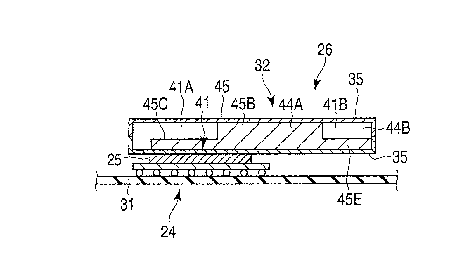
[0044]The wick 45 of the second embodiment includes a fourth projecting portion 52 projecting from the main portion 45A and the first projecting portion 45B to the second region 44B of the liquid returning flow path 44. The fourth projecting portion 52 projects to a region around the heat generating parts 25 in, for example, a semi-circular manner to correspond to the arrangement of the heat generating parts 25. The thickness of the fourth projecting portion 52 is set no more than a half of the thickness of the main portion 45A.

[0045]According to the second embodiment, the fourth projecting portion 52 projects to a position corresponding to the heat generating parts 25. With this arrangement, the cavity portion of the second region 44B of the liquid returning flow path 44 can be kept large. In this manner, the size of the fourth projecting portion 45F can be minimized. Thus, the fourth projecting portion 45E does not block the flow of the liquefied portion of the working fluid, and ...


PUM


Abstract

According to one embodiment, an electronic device includes a heat generating part housed inside a cabinet and a loop heat pipe housed inside the cabinet, which includes an internal flow path having a loop shape in which a working fluid is sealed. The loop heat pipe further includes a heat receiving unit, a heat radiating unit, a vapor flow path which allows a gasified portion of the working fluid to flow from the heat receiving unit towards the heat radiating unit, a liquid returning flow path which allows a liquefied portion of the working fluid to flow from the heat radiating unit towards the heat receiving unit, and a wick provided at a position adjacent to the vapor flow path inside the liquid returning flow path. The wick also serves as a partition portion which partitions the vapor flow path and the liquid returning flow path from each other.

Description

CROSS-REFERENCE TO RELATED APPLICATIONS[0001]This application is based upon and claims the benefit of priority from Japanese Patent Application No. 2008-048578, filed Feb. 28, 2008, the entire contents of which are incorporated herein by reference.BACKGROUND[0002]1. Field[0003]One embodiment of the present invention relates to an electronic device equipped with a loop heat pipe for cooling a heat generating part, a loop heat pipe and a cooling device.[0004]2. Description of the Related Art[0005]For example, a Japanese patent application, Jpn. Pat. Appln. KOKAI Publication No. 2004-324906 discloses a loop-shaped heat pipe having the following structure. This loop heat pipe includes a container inside which a loop-shaped flow path formed around, a wick provided in the flow path inside the container and a working fluid provided to fill the internal space of the container. The wick is formed of a cloth material which can exhibit a capillary action. The wick is provided in the section wh...

Claims


Application Information

Patent Timeline
Patent Type & Authority Patents(United States)
IPC IPC(8): H05K7/20H01L23/36
CPCG06F1/203G06F2200/201H01L2924/0002H01L2924/00
Inventor TOMIOKA, KENTARO
Owner TOSHIBA CLIENT SOLUTIONS CO LTD
Why Eureka
Try Eureka