Loop heat pipe

a technology of loop heat pipe and heat pipe body, which is applied in the direction of cooling/ventilation/heating modification, electrical equipment, solid-state devices, etc., can solve the problems of affecting the performance of heat transfer, the difficulty of cleaning, evacuating or exhausting the internal part of the pipe, the vacuum level of the pipe, etc., and achieves the effect of enhancing the sealing operation and easing the operation

Inactive Publication Date: 2010-02-02
JAFFE
View PDF13 Cites 14 Cited by
  • Summary
  • Abstract
  • Description
  • Claims
  • Application Information

AI Technical Summary

Benefits of technology

[0006]The present invention is to provide a loop heat pipe, which includes an evaporator and a closed loop. The connection of the evaporator and the closed loop can ease the operation for cleaning, evacuating or exhausting the loop heat pipe before sealing. Furthermore, the convenient connection procedure of the evaporator and the closed loop will enhance the performance of the sealing operation.

Problems solved by technology

After the pipes and the evaporator form a loop, it is very difficult to clean, evacuate or exhaust the internal part of the pipes.
Therefore, the cleanness and the degree of vacuum of the pipes become uncontrollable, which will affect the performance of heat transfer.
In this manner, the loop heat pipe will interfere the welding or the adhesion procedure.
However, the detachable torch requires additional steps for detaching and assembling the torch, which will largely slow down the production speed.
However, the melted soldering material can flow into the pipe, which will be absorbed by the capillary structure, thereby clogging the capillary structure.

Method used


Image

  • Loop heat pipe
  • Loop heat pipe
  • Loop heat pipe

Examples


Embodiment Construction

[0012]In order to better understanding the features and technical contents of the present invention, the present invention is hereinafter described in detail by incorporating with the accompanying drawings. However, the accompanying drawings are only for the convenience of illustration and description, no limitation is intended thereto.

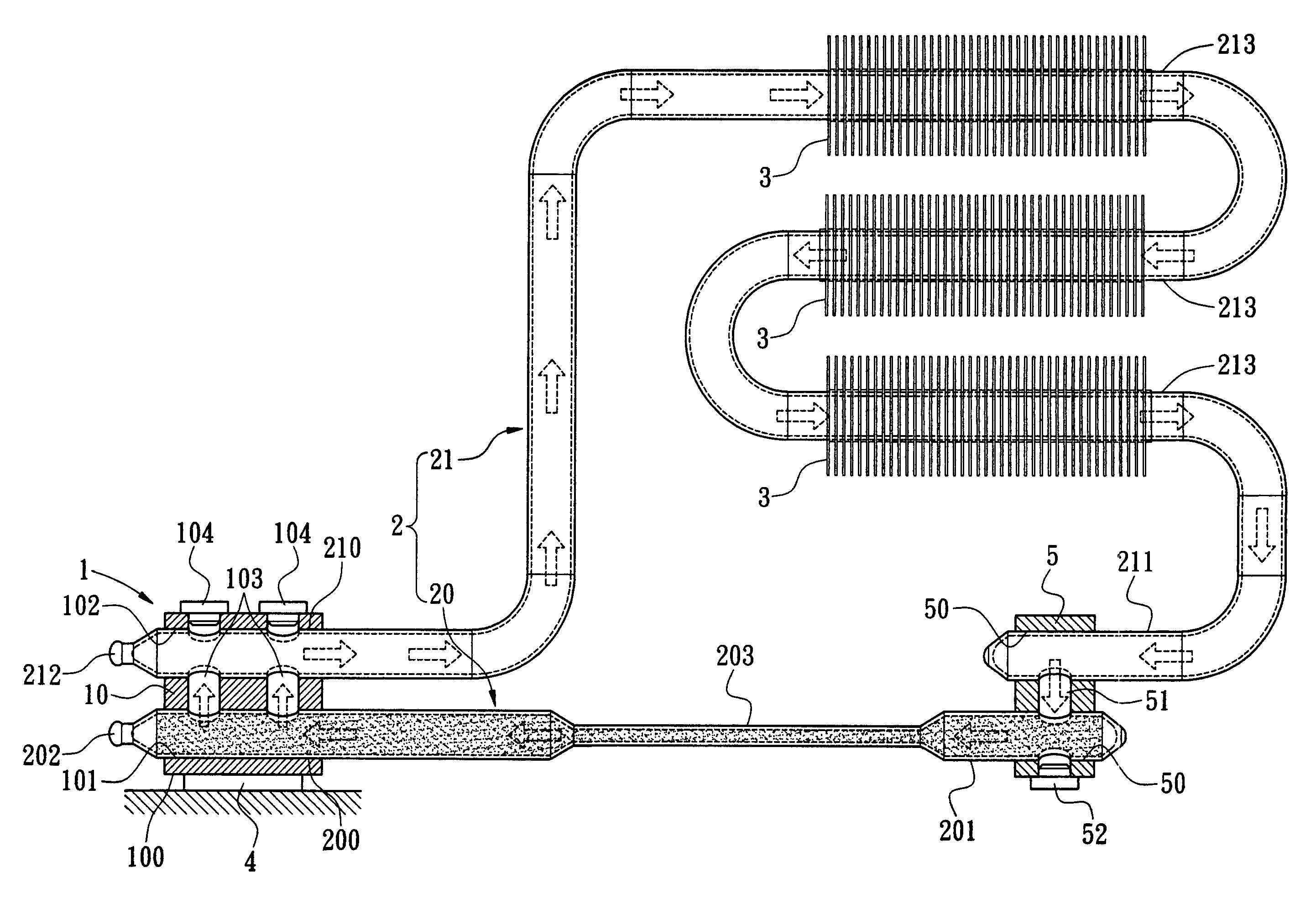
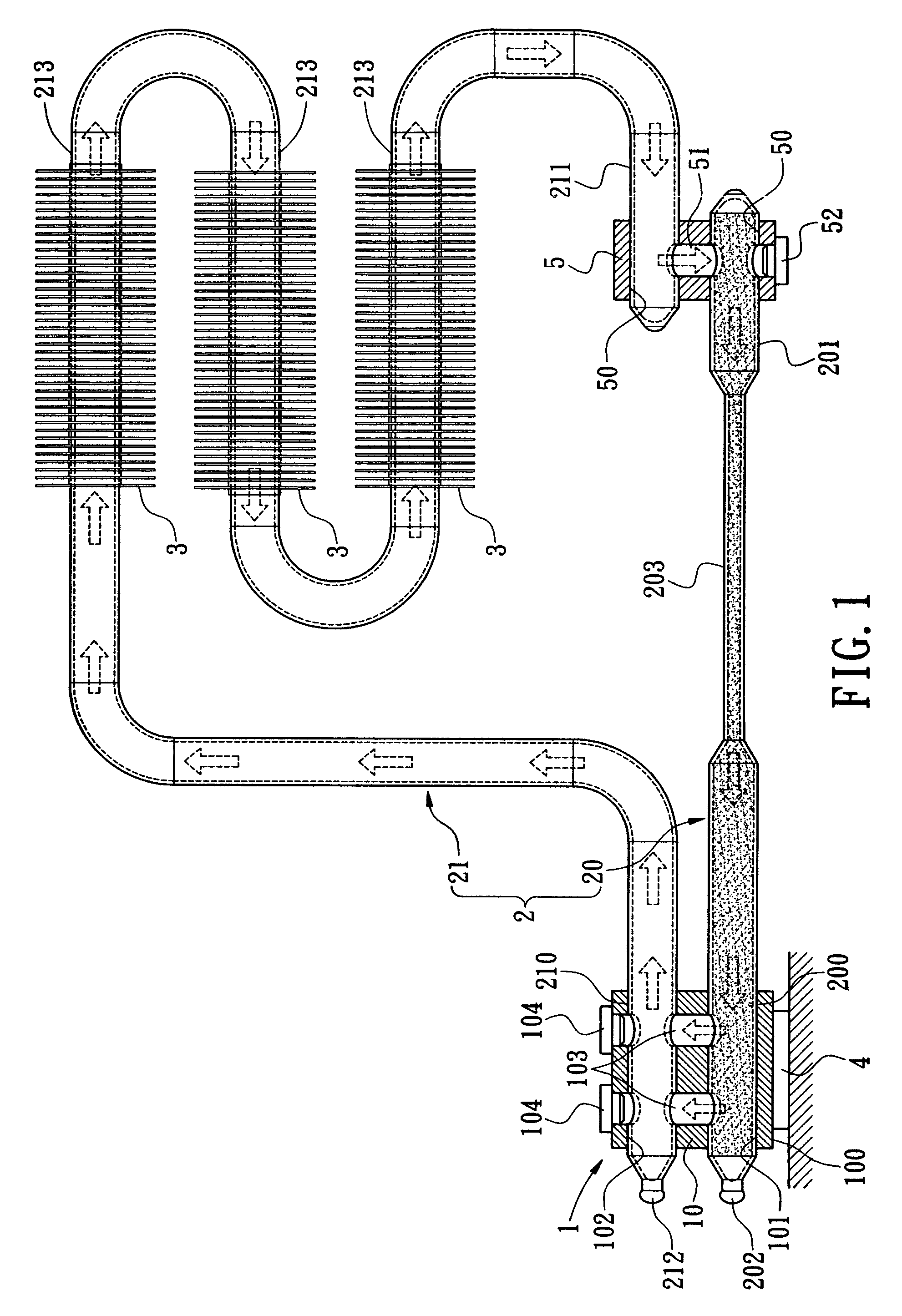
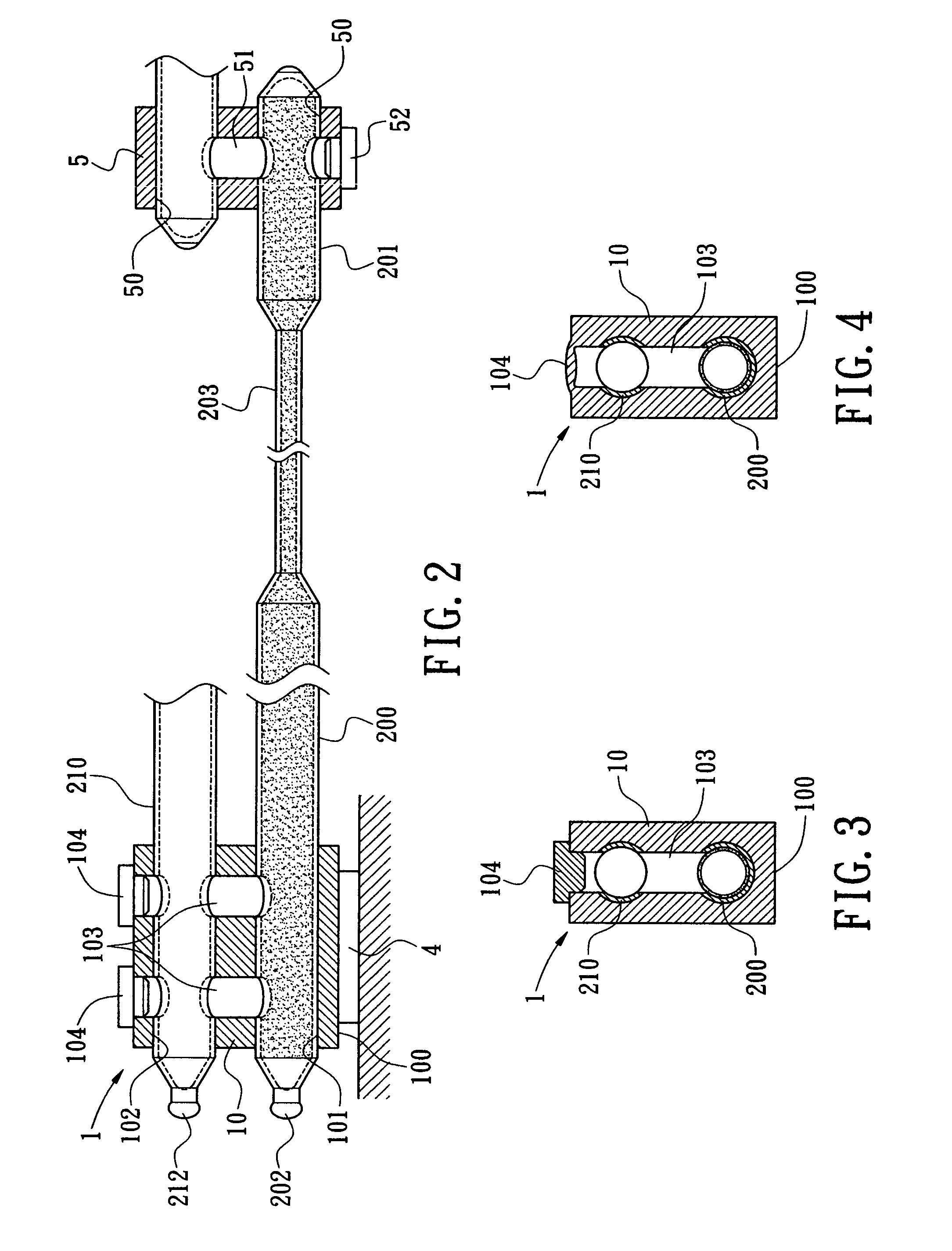
[0013]Referring to FIG. 1, a loop heat pipe in accordance with the first embodiment of the present invention is illustrated. As shown, the loop heat pipe includes an evaporator 1 and a sealed pipe 2.

[0014]The evaporator 1 is the portion that the loop heat pipe absorbs heat. The evaporator 1 includes a evaporator body 10 made of a heat conductive material, e.g. aluminum or copper. Therefore, the evaporator body 10 is substantially a heat spreader, which includes a contact surface 100 provided for contacting with a heat source 4. The heat source 4 is a heat generating electronic device. In one embodiment, the heat source 4 refers to a central processing...


PUM


Abstract

A loop heat pipe includes an evaporator and a closed loop. The evaporator includes an evaporator body made of a heat conductive material. The evaporator body has at least two retaining holes and at least a channel hole penetrating the retaining holes. In addition, the closed loop includes a first pipe body and at least a second pipe body. One end of the first and the second pipe bodies is a heat reception end, which are securely fastened to the two retaining holes of the evaporator. The other end of the first and the second pipe bodies is a heat reception end, thereby sequentially forming a circulating loop. Meanwhile, a flattened liquid seal region is formed between the heat reception end and the connection end of the first pipe body.

Description

BACKGROUND OF THE INVENTION[0001]The present invention relates generally to a loop heat pipe, and more particularly to an evaporator of the loop heat pipe.[0002]A loop heat pipe is a heat exchange system, wherein both the liquid and gas phase of the working fluid flow along the same direction. The working principle of the loop heat pipe is similar to that of the conventional heat pipe. However, the loop heat pipe does not comprise the drawback that the liquid phase of the working fluid flows along a direction opposite to that of the gas working fluid. Therefore, the performance of the loop heat pipe is much better than that of the conventional heat pipe.[0003]One conventional loop heat pipe is disclosed in Taiwanese Patent Application No. 92130196, entitled “method for manufacturing evaporator of loop heat pipe.” Although the primary subject matter disclosed in this application publication pertains to a method for manufacturing an evaporator of loop heat pipe, one can easily realize...

Claims


Application Information

Patent Timeline
Patent Type & Authority Patents(United States)
IPC IPC(8): H05K7/20
CPCF28D15/0266H01L23/427F28D15/043H01L2924/0002H01L2924/00
Inventor LI, JIA-HAO
Owner JAFFE
Why Eureka
Try Eureka