Method for manufacturing evaporator for loop heat pipe system

a manufacturing method and technology of evaporators, applied in the direction of semiconductor/solid-state device details, lighting and heating apparatus, electronic components used in various electronic devices such as computers, generate a large amount of heat during operation, and the performance of electronic devices is severely deteriorated, so as to improve the value of contact conductance, improve the manufacturing process, and reduce the effect of manufacturing cos

Inactive Publication Date: 2011-10-11
ZALMAN TECH CO LTD +1
View PDF8 Cites 13 Cited by
  • Summary
  • Abstract
  • Description
  • Claims
  • Application Information

AI Technical Summary

Benefits of technology

[0023]The present invention provides a method of manufacturing an evaporator for a loop heat pipe system by which not only a simple manufacturing process and a low manufacturing cost are possible but also a contact state between a sintered wick and a heating plate is improved, thereby increasing a value of contact conductance.

Problems solved by technology

Electronic parts such as CPUs or semiconductor chips used for various electronic devices such as computers generate a large amount of heat during operation.
Accordingly, when heat generated during the operation of an electronic device is not effectively cooled down, the performance of the electronic device is severely deteriorated and, in some cases, the electronic device itself may be damaged.
However, as nowadays many released electronic products are made slim, an installation distance between electronic parts generating heat during operation is continuously decreased so that heat is not appropriately cooled down.
Also, since the heat load of electronic parts has continuously increased due to the high integration and high performance of the electronic parts, the above-described cooling methods are not able to effectively cool down the electronic parts.
Although this problem is less severe in the case of the heat pipe of the thermosyphon system, a heat transport ability of the heat pipe is quite deteriorated when the condenser section is located lower than the evaporator section in the field of gravity.
Accordingly, since there is a limitation in the positional relationship between the constituent elements in the above two systems, this limitation prevents electronic devices employing the above cooling systems from being made slim.
Another problem is that the mixture may make the amount of heat actually transported less than that that can be ideally transported.
However, in a method of manufacturing an evaporator employed in the conventional loop heat pipe system, since the sintered wick having the channels that are the passage of vapor is separately manufactured and then coupled to the heating plate, the manufacturing process is complicated and the state of a coupling surface is not satisfactory.
However, in order to manufacture the conventional evaporator used for a loop heat pipe system, since the sintered wick with the vapor passage is coupled to the heating plate and vapor is generated from the boundary surface between the sintered wick and the heating plate, the method of directly installing the metal powder to the heating plate and sintering the metal power as in the above-described cylindrical heat pipe cannot be used.
Accordingly, a manufacturing process is complicated and a manufacturing cost is high.
In particular, since the coupling between the heating plate and the sintered wick is not satisfactory, a value of contact conductance is lowered so that heat transport is not effectively and sufficiently performed.
Also, according to the metal coupling method of primarily sintering the metal powder as sintered wick first and then sintering the sintered wick again), changes in the shape, size, porosity, and permeability of the sintered wick due to the fact that the contraction rate of the sintered wick cannot be avoided.

Method used


Image

  • Method for manufacturing evaporator for loop heat pipe system
  • Method for manufacturing evaporator for loop heat pipe system
  • Method for manufacturing evaporator for loop heat pipe system

Examples


Embodiment Construction

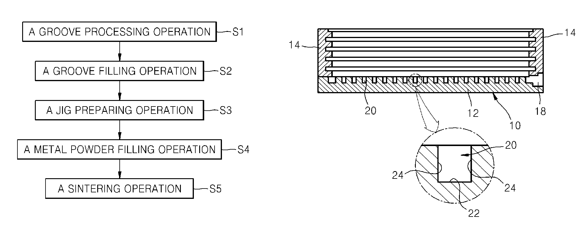
[0043]The attached drawings for illustrating exemplary embodiments of the present invention are referred to in order to gain a sufficient understanding of the present invention, the merits thereof, and the objectives accomplished by the implementation of the present invention. Hereinafter, the present invention will be described in detail by explaining exemplary embodiments of the invention with reference to the attached drawings. Like reference numerals in the drawings denote like elements.

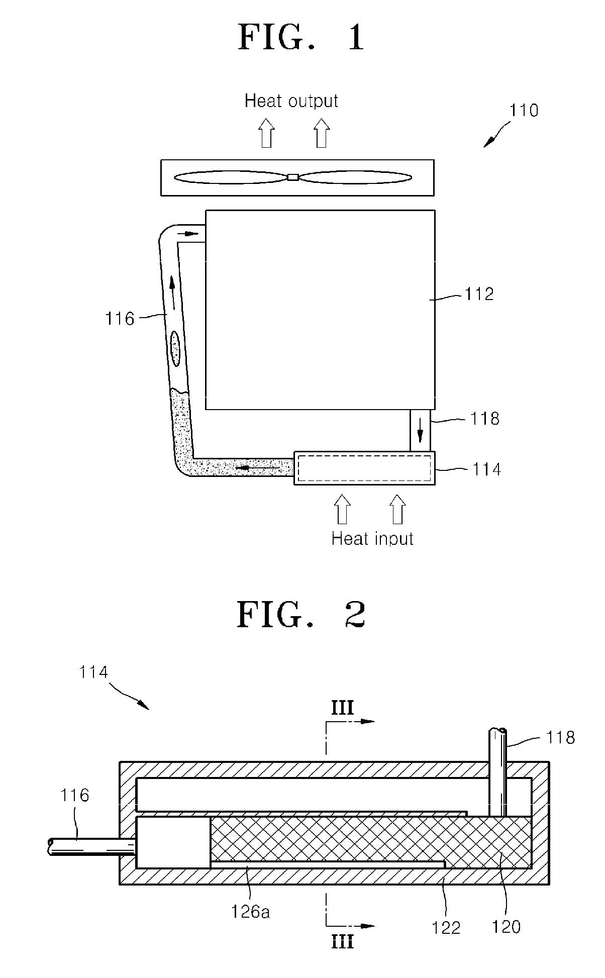
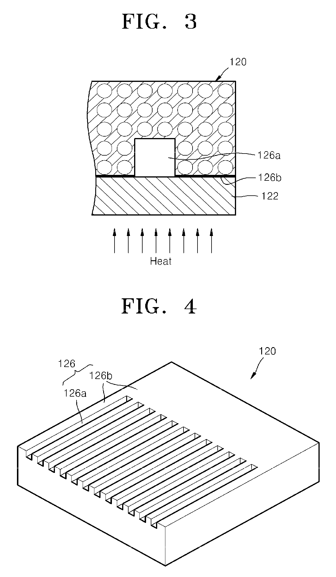
[0044]The present invention is related to an evaporator for a loop heat pipe system including a condenser, a vapor transport line, and a liquid transport line. FIG. 5 is a perspective view of a loop heat pipe system 200 including an evaporator 1 manufactured in a method according to an embodiment of the present invention. Referring to FIG. 5, the loop heat pipe system 200 includes the evaporator 1, a condenser 210, a vapor transport line 220, and a liquid transport line 230.

[0045]The condenser 21...


PUM

PropertyMeasurementUnit
temperatureaaaaaaaaaa
porosityaaaaaaaaaa
temperatureaaaaaaaaaa

Abstract

Provided is a method of manufacturing an evaporator for a loop heat pipe system including a condenser, a vapor transport line, and a liquid transport line, and more particularly, to a method of manufacturing an evaporator for a loop heat pipe system which provides a simple manufacturing process capable of improving a contact state between a sintered wick and a heating plate.

Description

CROSS-REFERENCE TO RELATED APPLICATIONS[0001]The present application is a continuation of pending International patent application PCT / KR2008 / 004495 filed on Aug. 1, 2008 which designates the United States and claims priority from Korean patent application 10-2008-0058984 filed on Jun. 23, 2008, the content of which is incorporated herein by reference.FIELD OF THE INVENTION[0002]The present invention relates to a method of manufacturing an evaporator for a loop heat pipe system including a condenser, a vapor transport line, and a liquid transport line, and more particularly, to a method of manufacturing an evaporator for a loop heat pipe system which provides a simple manufacturing process capable of improving a contact state between a sintered wick and a heating plate.BACKGROUND OF THE INVENTION[0003]Electronic parts such as CPUs or semiconductor chips used for various electronic devices such as computers generate a large amount of heat during operation. Such electronic devices are...

Claims


Application Information

Patent Timeline
Patent Type & Authority Patents(United States)
IPC IPC(8): B23P6/00
CPCF28D15/0266F28D15/043F28D15/046H01L23/427Y10T29/4935H01L2924/0002Y10T29/49353H01L2924/00
Inventor KIM, CHUL-JUSEO, MIN-WHANSUNG, BYUNG-HOYOO, JUNG-HYUNCHOI, JEE-HOONKI, JAE-HYUNG
Owner ZALMAN TECH CO LTD
Why Eureka
Try Eureka