Temperature actuated capillary valve for loop heat pipe system

a capillary valve and loop technology, applied in indirect heat exchangers, lighting and heating apparatus, etc., can solve problems such as excessive heat in the heat sink

Active Publication Date: 2015-09-29
THE UNITED STATES OF AMERICA AS REPRESENTED BY THE SECRETARY OF THE NAVY
View PDF29 Cites 13 Cited by
  • Summary
  • Abstract
  • Description
  • Claims
  • Application Information

AI Technical Summary

Problems solved by technology

When the side of the satellite having the condenser is facing toward the sun, the heat sink becomes too hot.

Method used


Image

  • Temperature actuated capillary valve for loop heat pipe system
  • Temperature actuated capillary valve for loop heat pipe system
  • Temperature actuated capillary valve for loop heat pipe system

Examples


Embodiment Construction

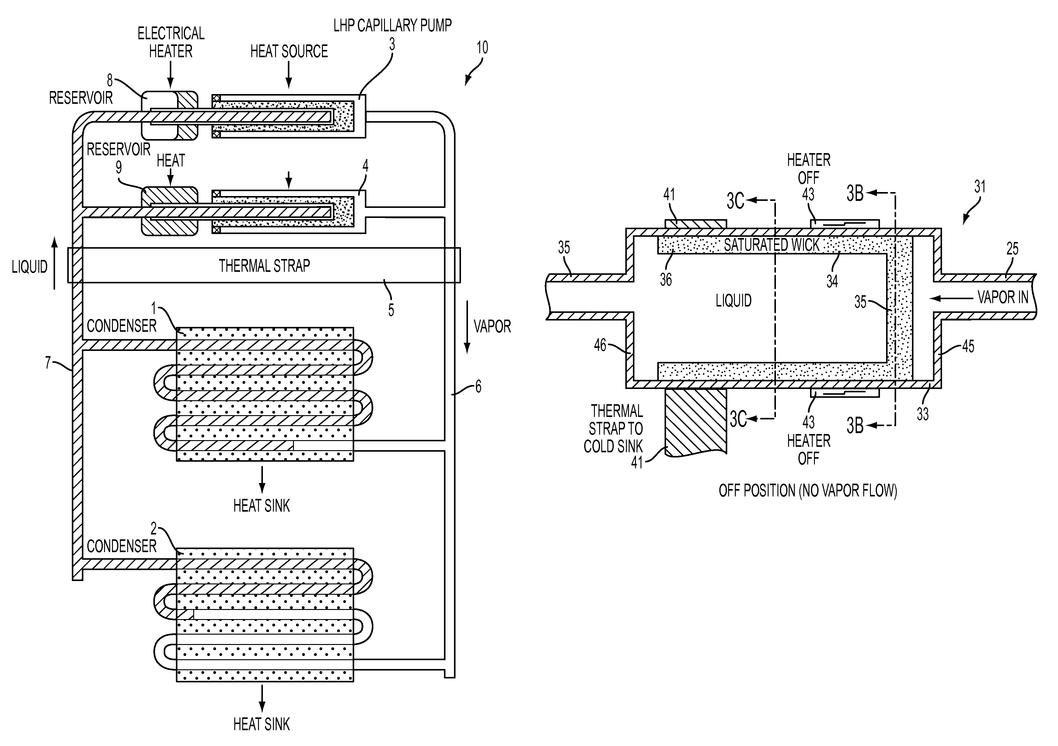
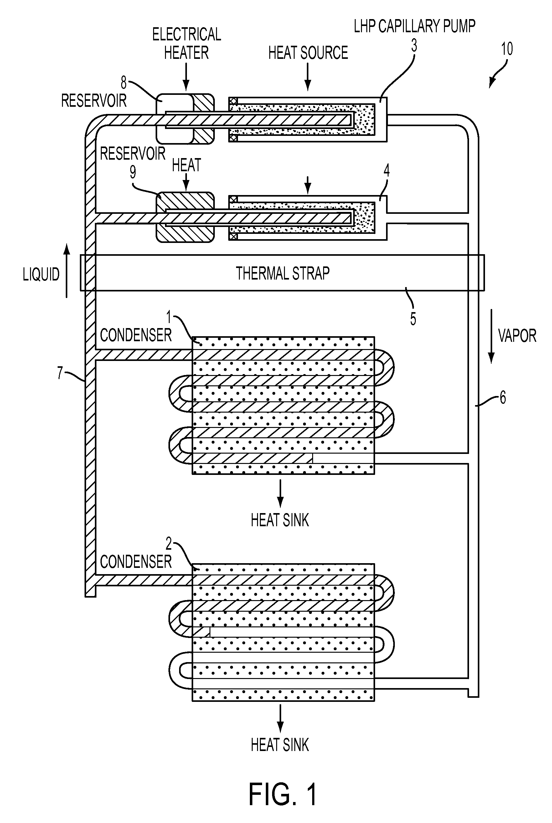
[0020]FIG. 1 illustrates an existing technology for temperature control in a two-phase heat transfer system. This example system has two condensers 1, 2 and two capillary pumps or evaporators 3, 4. Each capillary pump 3, 4 has an electrical resistance heater to control the temperature of the fluid in the reservoir 8, 9. A thermal strap 5 is attached to both the vapor conduit 6 and the liquid conduit 7. Inclusion of a thermal strap can reduce the required heater power to about five percent of the total heat transport. However, the thermal strap must be sized properly for the application. If the conductance value of the thermal strap is not sized properly, it can degrade the system performance, particularly in hot environments. In addition, in space-based systems, this temperature control system is completely dependent on the system operating conditions and the thermal environment once the spacecraft is in orbit. If a problem arises, it is difficult or impossible to correct while the ...


PUM


Abstract

A capillary flow valve for use in a two phase heat transfer system such as a loop heat pipe, including an inlet port for receiving working fluid in a vapor-phase, an outlet port for outputting working fluid in a vapor-phase, and a porous wick material extending across the interior of the valve. Heating the wick evaporates liquid-phase working fluid from the wick and allows the vapor-phase working fluid to pass through the wick to the outlet port. Removing the heat allows liquid to condense in the wick, preventing flow of the vapor-phase working fluid through the wick to the outlet port.

Description

CROSS REFERENCE TO RELATED APPLICATIONS[0001]This is a non-provisional of and claims priority under 35 USC 119(e) to U.S. Provisional Patent Application No. 61 / 647,593, filed in the United States on May 16, 2012, the entire disclosure of which is incorporated by reference herein.BACKGROUND[0002]1. Technical Field[0003]This is related to heat transfer devices, and more particularly, to loop heat pipe systems suitable for aerospace use.[0004]2. Description of Related Technology[0005]Two-phase heat transfer systems known as capillary heat pipes and loop heat pipes were first developed in the 1980s. U.S. Pat. No. 4,515,209 to Maidanik et al. describes the first known loop heat pipe, developed in the former Soviet Union in the early 1980s.[0006]The operating temperature of a two-phase heat transfer system is typically governed by the saturation temperature of its compensation chamber. One approach to thermal control has involved cold-biasing the compensating chamber and using an electric...

Claims


Application Information

Patent Timeline
Patent Type & Authority Patents(United States)
IPC IPC(8): F28D15/06F28D15/04
CPCF28D15/043F28D15/06
Inventor HOANG, TRIEM T.
Owner THE UNITED STATES OF AMERICA AS REPRESENTED BY THE SECRETARY OF THE NAVY
Why Eureka
Try Eureka