Bearing unit and rotation drive device using the same

A technology of rotating drive device and bearing, applied in the direction of bearing components, rigid brackets of bearing components, bearings, etc., can solve problems such as leakage of lubricating oil, and achieve the effect of reducing discreteness

Inactive Publication Date: 2005-11-16
SONY CORP
View PDF8 Cites 11 Cited by
  • Summary
  • Abstract
  • Description
  • Claims
  • Application Information

AI Technical Summary

Problems solved by technology

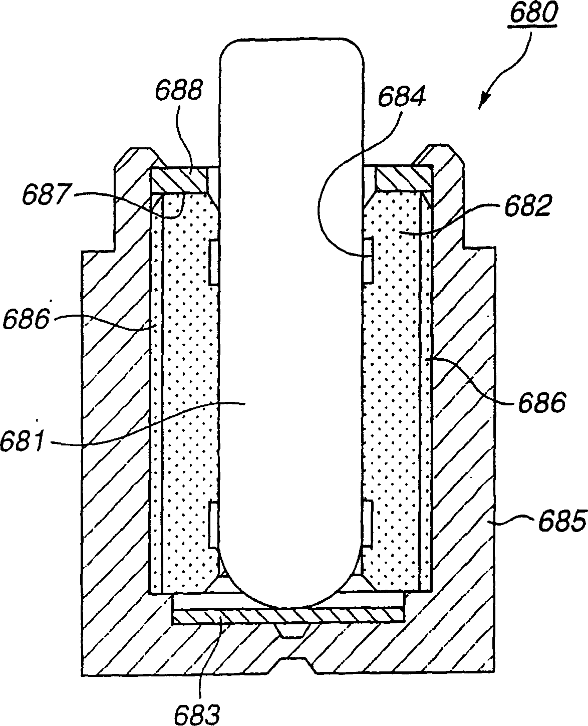
[0027] image 3 The bearing unit 680 shown has a structure that surrounds the bearing body with two parts, the bearing sleeve 685 and the elastic body 688. Therefore, there is a possibility that lubricating oil leaks from the joint between the bearing sleeve 685 and the elastic body 688. possibility of

Method used


Image

  • Bearing unit and rotation drive device using the same
  • Bearing unit and rotation drive device using the same
  • Bearing unit and rotation drive device using the same

Examples


Embodiment Construction

[0091] Below, preferred embodiments of the present invention will be described with reference to the accompanying drawings.

[0092] The bearing unit involved in the present invention can be used for installation in Figure 4 In the motor in the notebook computer 1 shown.

[0093] Such as Figure 4 As shown, the computer 1 has a display unit 2 and a main unit 3, and the display unit 2 is connected to the main unit 3 through a connection unit 4 so as to be rotatable. The host 3 has a keyboard 5 and a casing 12 . A heat sink 10 is disposed inside the casing 12 .

[0094] Figure 5 yes Figure 4 The V-V cross-sectional view of the housing 12, Image 6 yes to set in Figure 5 The perspective view showing the heat sink 10 inside the housing 12 is shown.

[0095] Such as Figure 5 As shown, the housing 12 accommodates the heat sink 10 . The heat sink 10 has Image 6 structure shown. The heat sink 10 is also called a cooling device, and has a base 20 made of metal, a moto...


PUM


Abstract

A bearing unit ( 90 ) for rotatably supporting a shaft ( 100 ) comprises a seamless holding member ( 120 ) with a gap allowing a shaft to run through and extend to the outside, a bearing ( 130 ) arranged in the inside of the holding member to rotatably support the shaft so as to make it radially revolvable, an anti-shaft-release member ( 115 ) fitted to the shaft so as to abut the bearing in order to prevent the shaft from slipping away in the thrusting direction and a space-forming member ( 113 ) arranged in the inside of the holding member so as to secure a space around the anti-shaft-release member. A bearing unit may further comprise an lubricating oil seal member and the space-forming member may be used to form a passage way for lubricating oil to prevent lubricating oil from leaking.

Description

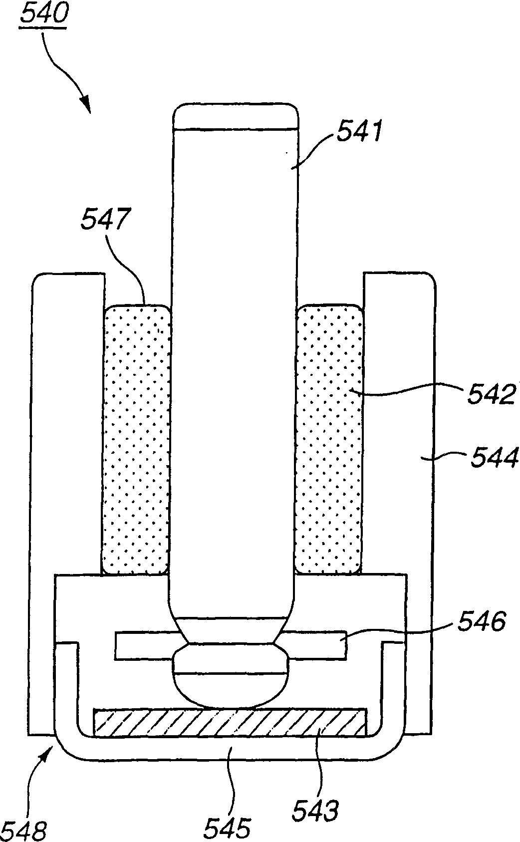
technical field [0001] The present invention relates to a bearing unit that rotatably supports a shaft, and a rotary drive device using the bearing unit. [0002] This application is based on Japanese Invention Patent Application No. 2003-300529 filed in Japan on August 25, 2003, Japanese Invention Patent Application No. 2003-053231 filed on February 28, 2003, and January 10, 2003 Priority is claimed on the basis of Japanese Invention Patent Application No. 2003-004928 filed, and these applications are incorporated herein by reference. Background technique [0003] The shaft is rotatably supported by a bearing unit, which is provided, for example, in a rotary drive device such as a fan motor. [0004] The shape of the shaft of the bearing unit of this structure is I-shape (it is also called linear type), and it is rotatably supported using lubricating oil. Specifically, there is an example described in Japanese Patent No. 3265906. The bearing unit 540 described in this pu...

Claims


Application Information

Patent Timeline
Patent Type & Authority Applications(China)
IPC IPC(8): F16C33/08F16C17/02F16C17/08F16C33/10F16C35/02H02K5/167
Inventor 宍户祐司矢泽健一郎金子猛高田清幸佐藤弘史柿沼义昭中村一郎
Owner SONY CORP
Why Eureka
Try Eureka