Rotation speed reducing structure of dust collection chamber cap of vacuum cleaner

A technology of vacuum cleaner and deceleration structure, which is applied in the direction of suction filter, etc., can solve problems such as bruising hands, achieve the effect of reducing impact noise and preventing safety accidents

Inactive Publication Date: 2005-11-23
LG ELECTRONICS (TIANJIN) APPLIANCES CO LTD
View PDF0 Cites 19 Cited by
  • Summary
  • Abstract
  • Description
  • Claims
  • Application Information

AI Technical Summary

Problems solved by technology

In addition, due to the high strength when the dust collection chamber cover (23) is closed, there is also the possibility of bruising your hands.

Method used


Image

  • Rotation speed reducing structure of dust collection chamber cap of vacuum cleaner
  • Rotation speed reducing structure of dust collection chamber cap of vacuum cleaner
  • Rotation speed reducing structure of dust collection chamber cap of vacuum cleaner

Examples


Embodiment Construction

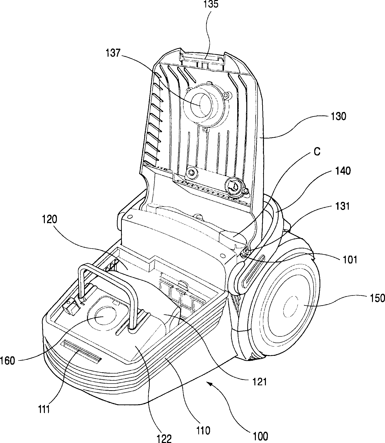
[0041] Such as image 3 , 4 As shown, the interior of the vacuum cleaner body (100) of the present invention is equipped with several components, and the lower part of such a body (100) forms a body base (110). The front half of the upper part of the main body bottom case (110) forms a dust collection chamber (120), and foreign matter such as dust in the air will be collected in the dust collection chamber (120) after being filtered out. A dust collection assembly (122) is installed inside the dust collection chamber (120), and the dust collection assembly (122) includes a dust collection bag (121) for collecting dust.

[0042]A moving handle (140) for moving the body (100) is formed at approximately the central part of the body bottom case (110), so that it is more convenient to move the body (100) over a long distance. In addition, a pair of moving wheels (150) are installed on the left and right sides of the rear end of the body bottom shell (110), and the body (100) can ...


PUM


Abstract

The invention provides a rotation speed reducing structure of dust collection chamber cap of vacuum cleaner, characterized by that the arrangement comprises a dust collection chamber cover and a speed reduction projection, wherein the dust collection chamber cover is arranged on one side of the bottom casing of the body member for opening and closing the dust collection chamber, the speed reduction projection can slow down the rotational speed of the dust collection chamber cover.

Description

technical field [0001] The invention relates to a rotation deceleration structure of a dust collection chamber cover of a vacuum cleaner. Background technique [0002] Generally speaking, a vacuum cleaner is a cleaning appliance, which can generate a strong suction force inside the vacuum cleaner body, and can use this suction force to forcibly suck dust on the ground through a suction nozzle (nozzle). Recently, this kind of vacuum cleaner is used in most general households, and since the vacuum cleaner with strong suction power is required when cleaning carpets and sofas, the use of the vacuum cleaner has become more and more widespread. [0003] Such as figure 1 As shown, the vacuum cleaner is made of the following parts: a body (20), which is equipped with several parts inside; a connecting hose (hose) (40), which is made of a material with certain flexibility, and it is connected with The interior of the main body (20) is connected; the extension pipe (60), which is co...

Claims


Application Information

Patent Timeline
Patent Type & Authority Applications(China)
IPC IPC(8): A47L9/14
Inventor 郑再德
Owner LG ELECTRONICS (TIANJIN) APPLIANCES CO LTD
Why Eureka
Try Eureka