Unmanned aerobat with ring-like wing

A technology for unmanned aerial vehicles and aircraft, applied in the field of unmanned aerial communication and transmission tools, can solve problems such as the development of productivity and the progress of science and technology, increase of personnel and financial and material resources, and limit the development and use of unmanned aerial vehicles. Cleverly designed, easy to maintain, fast results

Inactive Publication Date: 2005-11-23
王忠信
View PDF0 Cites 15 Cited by
  • Summary
  • Abstract
  • Description
  • Claims
  • Application Information

AI Technical Summary

Problems solved by technology

[0002] At present, known unmanned aerial vehicles are widely used by all walks of life due to their wide application range, low cost, and strong usability. However, it cannot be widely used, and its launch and recovery require a large space, especially when it comes to flight stability and easy control, which are important issues for UAVs
This makes the use of unmanned aerial vehicles still blank in many fields, especially in military reconnaissance, communication transmission, etc. The requirements are more stringent, which greatly limits the development and use of unmanned aerial vehicles. had to abandon the use of unmanned aerial vehicles
Thereby increasing the loss of personnel, financial and material resources, etc., which directly or indirectly hinder the development of productivity and the progress of science and technology.

Method used


Image

  • Unmanned aerobat with ring-like wing
  • Unmanned aerobat with ring-like wing
  • Unmanned aerobat with ring-like wing

Examples


Embodiment Construction

[0017] The present invention will be described in further detail below in conjunction with the accompanying drawings.

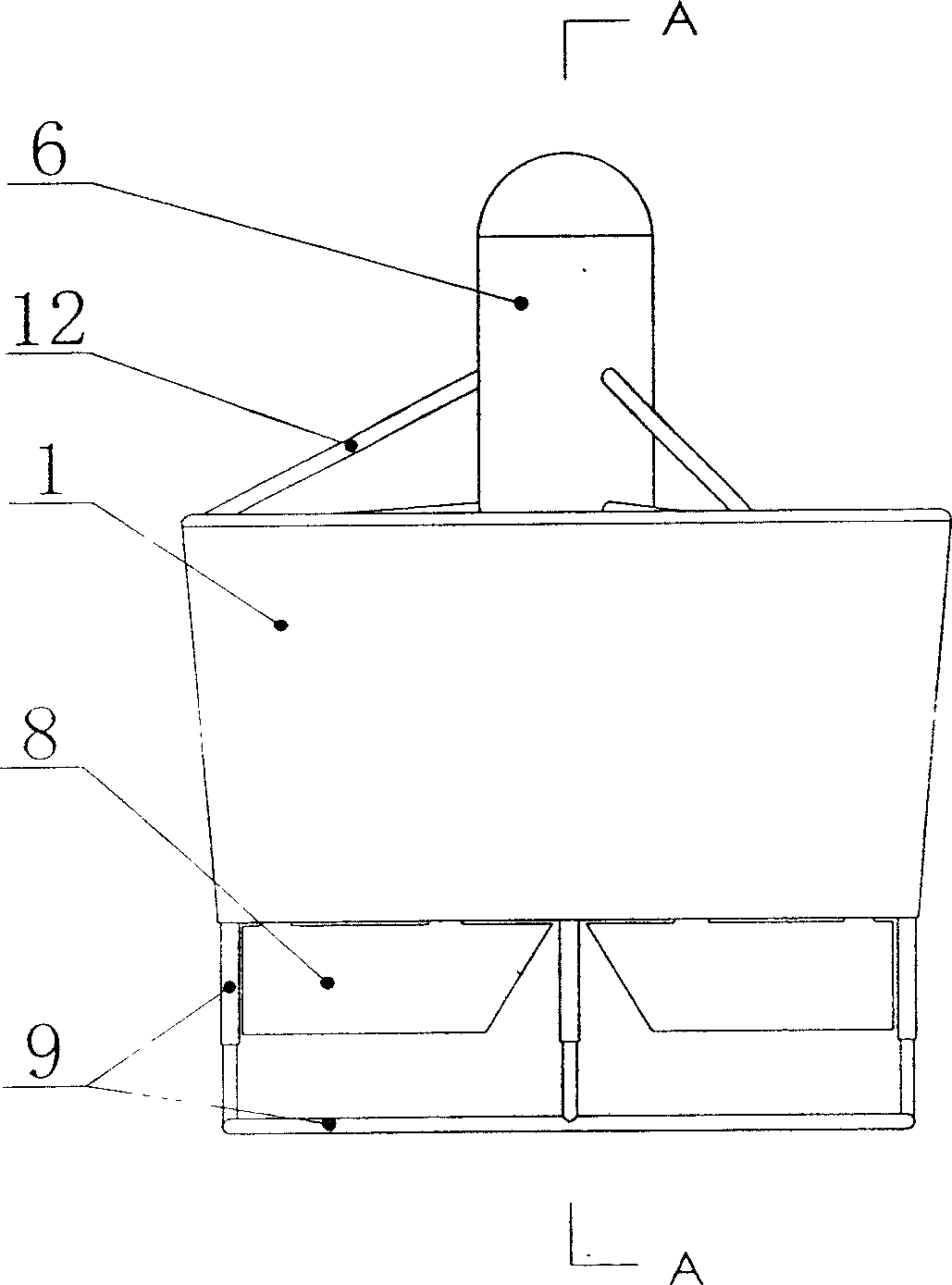
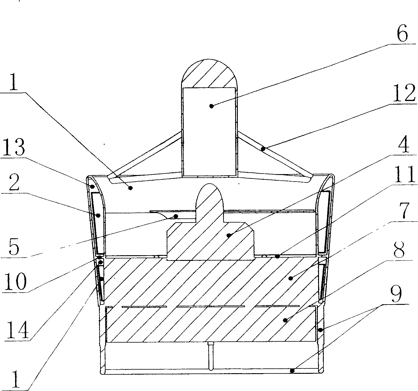
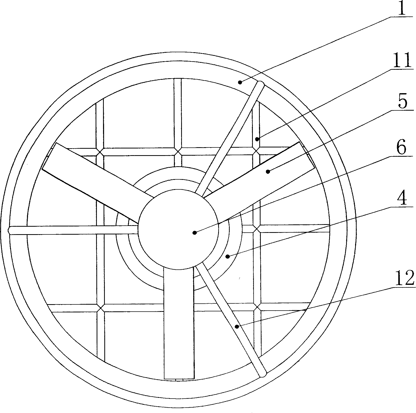
[0018] Depend on Figure 1-Figure 4 It can be seen that the present invention is: in the duct 1 of the cavity, the duct cavity is divided into two chambers 13, 14 up and down by the dividing plate 10, the fuel tank 2 of the aircraft is installed in the upper chamber 13, and the fuel tank 2 of the aircraft is installed in the lower chamber 14. The control instrument loading compartment 3 of the aircraft is installed, the engine 4 is installed at the center of the duct 1, the lower end of the engine 4 is equipped with a fixed rod 11 to connect with the inner wall of the duct 1, the propeller 5 is installed at the upper end of the engine 4, and the center of the duct 1 The upper end is provided with a load bin 6, on which there is a bracket 12 connected to the outer wall of the duct 1, the lower part of the fixed rod 11 is installed with a guide vane 7 connected...


PUM


Abstract

This invention relates to a ring-foil unattended airplane, wherein the divider divides the volume into two-piece volumes in an empty ducted, the upper volume has the airplane's fuel tank in it, and the down volume has the airplane's control embarkation storehouse in it, the center part of the ducted has the engine, and the down part of the engine is assembled with the fixed bar, which connects with the ducted inwall, the upper end of the engine has the locking, and the upper end of the duct's center part has the load storehouse, wherein the frame connects with the ducted outwall, the down part of the fixed bar has the blind, which connects with the ducted inwall, the bottom end of the blind has the vane, and the bottom end of the ducted has the airplane frame.

Description

technical field [0001] The invention relates to an unmanned flight communication transmission tool, which can take off and land vertically, and can realize real-time data transmission, and has the characteristics of all-weather flight. Background technique [0002] At present, known unmanned aerial vehicles are widely used by all walks of life due to their wide application range, low cost, and strong usability. However, it cannot be widely used, and its launch and recovery require a large space, especially when it comes to flight stability and easy control, which are important issues faced by UAVs. This makes the use of unmanned aerial vehicles still blank in many fields, especially in military reconnaissance, communication transmission, etc. The requirements are more stringent, which greatly limits the development and use of unmanned aerial vehicles. The use of unmanned aerial vehicles had to be abandoned. As a result, the loss of personnel, financial resources, and mater...

Claims


Application Information

Patent Timeline
Patent Type & Authority Applications(China)
IPC IPC(8): B64C27/20
Inventor 王忠信青泉孙树生吴世海丛林枝
Owner 王忠信
Why Eureka
Try Eureka