Robot knuckle actuating range limitation device for equipping movement area checking device

A technology for detection devices and action areas, which is applied to manipulators, manufacturing tools, program-controlled manipulators, etc., can solve problems such as increased working hours, unfavorable prices, and large parts, and achieves improved maintainability, reduced set-up man-hours, and increased set-up density. Effect

Inactive Publication Date: 2005-11-30
FANUC LTD
View PDF0 Cites 11 Cited by
  • Summary
  • Abstract
  • Description
  • Claims
  • Application Information

AI Technical Summary

Problems solved by technology

Therefore, in this case, each part is relatively large, or the operation man-hours required for the installation of the robot as a whole are increased in order to install the motion region detection and restriction device.
Furthermore, large components are also disadvantageous in terms of price, so miniaturization is desired

Method used


Image

  • Robot knuckle actuating range limitation device for equipping movement area checking device
  • Robot knuckle actuating range limitation device for equipping movement area checking device
  • Robot knuckle actuating range limitation device for equipping movement area checking device

Examples


Embodiment Construction

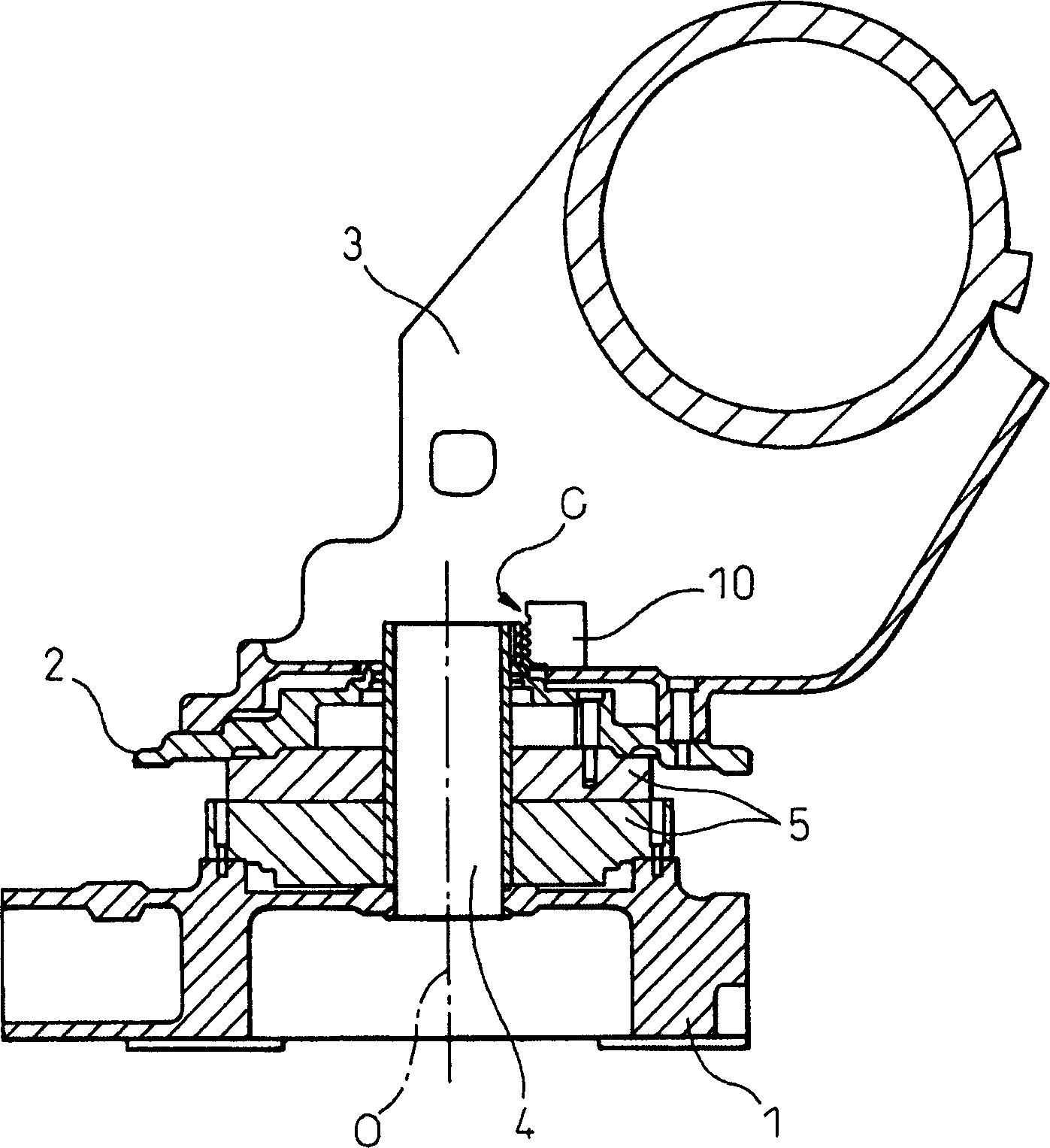
[0023] Below, refer to Figure 3 ~ Figure 6 Embodiments of the present invention will be described.

[0024] first, image 3 It is a cross-sectional view showing a joint portion of a robot equipped with a motion range detection and restriction device according to an embodiment of the present invention. image 3 Among them, symbol 1 is the first component corresponding to the J1 base (first connector base), which is fixed on the frame of the reducer 5 . In addition, reference numeral 2 is a second member (table member) fixed to the output shaft of the speed reducer 5, and is connected and fixed to a third member 3 corresponding to the J2 base (second connector base). On the other hand, the input shaft of the speed reducer 5 is coupled to an unillustrated motor (for driving the J1 axis).

[0025] Here, the speed reducer 5 constitutes a joint together with the second member 2 and has a known structure in which a hollow portion extends along the rotation axis O. As shown in FIG...


PUM


Abstract

An operation region detection device includes a dog, a support member for supporting it, and a detection switch outputting a signal based on contact or noncontact with the corresponding dog. The support member is arranged in a hollow part of a joint of a robot and attached to one of two link members of the robot rotatable relative to each other so that a center axis of the support member is substantially aligned with a rotation axis of relative rotation of the two link members. The dog is attached to the outer circumference of the support member and has a length corresponding to a predetermined detection region along a peripheral direction of the outer circumference. The detection switch is provided on the other of the two link members at a position facing the dog to detect a region to which a current position of the relative rotation belongs based on the state of output of the signal. An operation range restricting device for restricting an operation range of the relative rotation based on a region to which a current position of the detected relative rotation belongs.

Description

technical field [0001] The present invention relates to a motion range detecting device for detecting a region to which a current position of the relative rotation belongs at a joint part having a hollow structure in which two link members of a robot relatively rotate, and a motion range limiting device for a robot joint using the device. Background technique [0002] As a safety measure to ensure the safety of people performing work around industrial robots (hereinafter referred to as 'robots'), the following functions are generally used, that is, to monitor the position and / or posture of the robot, and to monitor the position and / or posture of the robot, and to detect when the robot accidentally enters or is about to enter a person. If it is within the working space, issue a warning and stop the robot. In addition, the same function is used in order to prevent interference between peripheral equipment and adjacent robots even when no human being is performing work around t...

Claims


Application Information

Patent Timeline
Patent Type & Authority Applications(China)
IPC IPC(8): B25J19/00B25J9/10
CPCB25J9/101
Inventor 冈田毅内田博大江将司
Owner FANUC LTD
Why Eureka
Try Eureka