Method for making a waveguide microwave antenna

A waveguide and microwave technology, applied to antennas, waveguide horns, electrical components, etc., can solve problems that affect the production cost of antennas and limit the number of molds

Inactive Publication Date: 2005-11-30
INTERDIGITAL CE PATENT HLDG
View PDF1 Cites 5 Cited by
  • Summary
  • Abstract
  • Description
  • Claims
  • Application Information

AI Technical Summary

Problems solved by technology

Due to high volume, low cost production, the number of molds required to manufacture the various components of this antenna is limited
Moreover, the alignment and interconnection of the various components of the antenna to prevent electrical discontinuities creates manufacturing constraints that affect the cost of producing the antenna

Method used


Image

  • Method for making a waveguide microwave antenna
  • Method for making a waveguide microwave antenna
  • Method for making a waveguide microwave antenna

Examples


Embodiment Construction

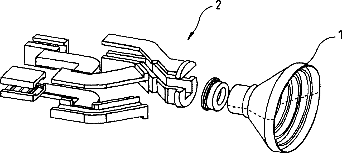
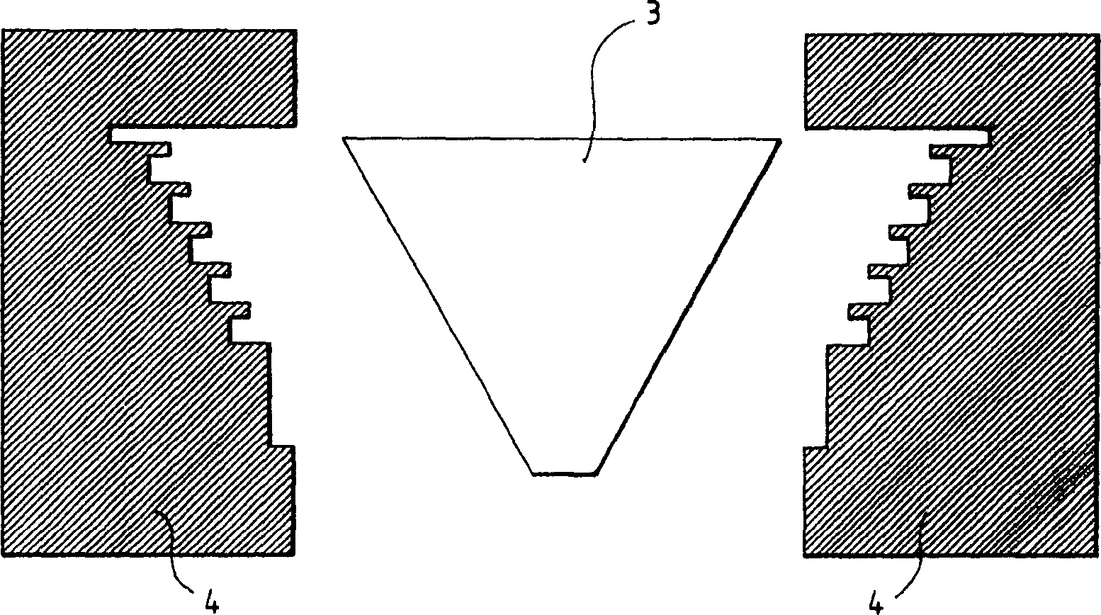
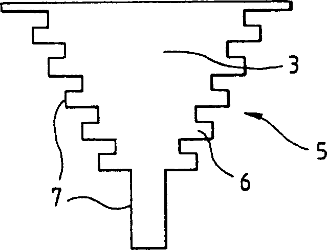
[0022] figure 2 A substantially conical preform from a block 3 of synthetic foam material is shown. The preform is made conformal in the mold 4 by hot pressing, so as to form image 3 The corrugated horn 5 is shown. Here, the synthetic foam material is a commercially available polymethacrylimide foam material named "ROHACELL HF". The bellows 6 are formed on the outer surface of the foam block 3 by thermoforming. The surface of the conformal foam block 3 is then metallized to form the corrugated horn. The thick lines on the outer surface of the foam block 3 represent the metallic coating of the foam block.

[0023] Figure 4 A substantially cylindrical preform from a block 3' of synthetic foam material is shown. The preform is made conformal in the mold 4' by hot pressing, so as to form Figure 5 The polarizer shown in 8. The conformal process consists in forming in the foam block 3' two radial grooves 9 and 10 symmetrical in the axial plane of the cylindrical foa...


PUM


Abstract

The invention concerns a method for making a waveguide microwave antenna with corrugated horn (5), which consists in forming the corrugations of the horn on the outer surface of a synthetic material foam block followed by surface metallization of the foam block configured to produce the antenna.

Description

technical field [0001] The invention relates to a manufacturing method of a microwave corrugated horn antenna utilizing waveguide technology. Background technique [0002] Antennas of this type generally consist of several molded parts. In particular, for the manufacture of corrugated horns, the method is to mold two halves which are symmetrical with respect to the axial plane of the horn. In view of high volume, low cost production, the number of molds required to manufacture the various components of such antennas is limited. Furthermore, the alignment and interconnection of the various components of the antenna to prevent electrical discontinuities create manufacturing constraints that affect the cost of producing the antenna. [0003] figure 1 A perspective view of an example of a microwave antenna comprising a corrugated horn 1 with a frequency separator 2 using waveguide technology is shown. The corrugated horn 1 is formed by assembling two symmetrical halves. [...

Claims


Application Information

Patent Timeline
Patent Type & Authority Applications(China)
IPC IPC(8): B29C43/02H01Q13/02
CPCB29K2105/04H01Q13/0291H01Q13/0208B29C43/021B29K2105/251Y10T29/49016
Inventor 阿里·卢齐耶多米尼克·洛海因东弗洛朗·阿韦蒂克里斯蒂安·佩尔松让-菲利普·库佩
Owner INTERDIGITAL CE PATENT HLDG
Why Eureka
Try Eureka