Holographic data recording apparatus and method

A data recording and holographic technology, applied in data recording, optical recording/reproduction/erasing methods, holographic technology, etc., can solve the problems of increasing the cost and difficulty of holographic data recording devices, reducing recording speed, etc.

Inactive Publication Date: 2005-12-14
MAPLE VISION TECH
View PDF1 Cites 3 Cited by
  • Summary
  • Abstract
  • Description
  • Claims
  • Application Information

AI Technical Summary

Problems solved by technology

[0011] However, conventional holographic data recording devices have the problem that in order to reflect the reference beam toward the disk-shaped holographic medium at a desired incident angle, it is necessary to use a conical mirror having a specific base angle that can provide the required required angle of incidence
Thus, in order to record multiple pieces of

Method used


Image

  • Holographic data recording apparatus and method
  • Holographic data recording apparatus and method
  • Holographic data recording apparatus and method

Examples


Example Embodiment

[0049]

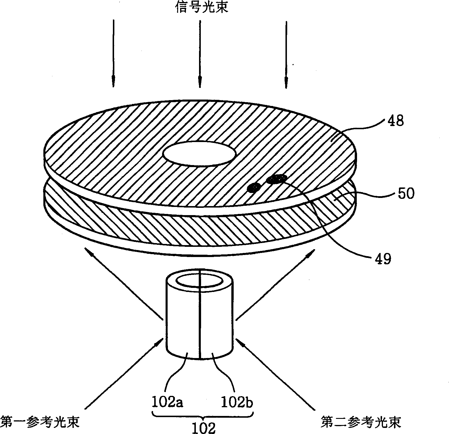
[0050] In the first preferred embodiment described above, the cylindrical optical body 102 is constructed by combining two cylindrical mirrors 102a and 102b so that the focus axis A of the cylindrical optical body 102 is located on the central axis of the holographic medium 50. However, combining the two cylindrical mirrors 102a and 102b requires high machining accuracy, such as Figure 5 As shown in , if the cylindrical mirrors 102a and 102b are not precisely bonded to each other, a scattered light beam will be generated at the contact interface between the cylindrical optical body 102a and the cylindrical optical body 102b. Therefore, in the second preferred embodiment, a non-reflective plate of fixed thickness is inserted between the two cylindrical mirrors constituting the cylindrical optical body, thereby facilitating the manufacture of the cylindrical optical body and preventing Scattered light beams are produced at the contact interface.

[0051] Figure 7 ...


PUM


Abstract

A holographic data recording device, comprising: a signal beam patterning unit, used to radiate a signal beam to a holographic medium, the signal beam includes a data pattern to be recorded; a cylindrical optical body, including a cylindrical reflecting surface, through which the cylindrical optical body makes The first and second reference beams that are alternately incident on it at respective incident angles are alternately reflected toward the holographic medium; the incident angle control unit is used to control the incident angles of the first and second reference beams incident on the cylindrical optical body , wherein the data pattern is recorded on the holographic medium by interference of the signal beam with the first and second reference beams on the holographic medium. The holographic data recording device does not need to replace conventional conical mirrors when recording a lot of data on the holographic medium, thereby increasing the recording speed and reducing its manufacturing cost.

Description

field of invention [0001] The present invention relates to a holographic data recording device and method; in particular, to a holographic data recording device and method capable of recording multiple pieces of holographic data on a holographic medium through angle multiplexing by using a columnar optical body. Background of the invention [0002] Conventional holographic memory systems generally adopt a page-by-page storage method. An input device such as an SLM (spatial light modulator) displays the data to be recorded in a two-dimensional array (called a page), while a detector array such as a CCD camera is used to retrieve the recorded data on readout . Other structures have also been proposed in which bit-by-bit recording is used instead of the page-by-page approach. However, all of these systems suffer from the common disadvantage that they need to record a huge number of individual holograms in order to fill the memory up to its maximum capacity. A typical page-or...

Claims


Application Information

Patent Timeline
IPC IPC(8): G11B7/0065
CPCG03H1/0465G03H1/265G03H2223/24G11B7/0065G11B7/10G11B7/1362G11B7/1395G11B7/24035
Inventor 文轸培
Owner MAPLE VISION TECH
Why Eureka
Try Eureka