
Optical recording medium, optical recording medium producing apparatus and optical recording medium producing method

A technology for recording media and recording information, which is applied in the direction of optical record carrier, optical record carrier manufacturing, optical recording/reproduction, etc. It can solve the problems of inability to read, overwrite and reproduce control data, and inability to stably execute DVD- RW synchronous detection and other problems, to achieve the effect of accurate synchronous control

Inactive Publication Date: 2005-12-14
PIONEER CORP
View PDF1 Cites 0 Cited by
  • Summary
  • Abstract
  • Description
  • Claims
  • Application Information

AI Technical Summary

Problems solved by technology

As a result, even if other reproduction control data are overwritten in this area, the reproduction signal of the overwriting data interferes with the reproduction signal of the embossed pit point string so that it cannot be read out, so basically it is impossible to overwrite other reproduction control data.
[0006] However, since the area where embossed pit point strings are embedded is equal to the area where tracks are intermittently formed, the output level of the wobble signal extracted from this area is lower than that of the wobble signal extracted from the area where continuous tracks of recording data are recorded. output level, so DVD-RW sync detection cannot be performed stably

Method used


Image

  • Optical recording medium, optical recording medium producing apparatus and optical recording medium producing method
  • Optical recording medium, optical recording medium producing apparatus and optical recording medium producing method
  • Optical recording medium, optical recording medium producing apparatus and optical recording medium producing method

Examples


specific example

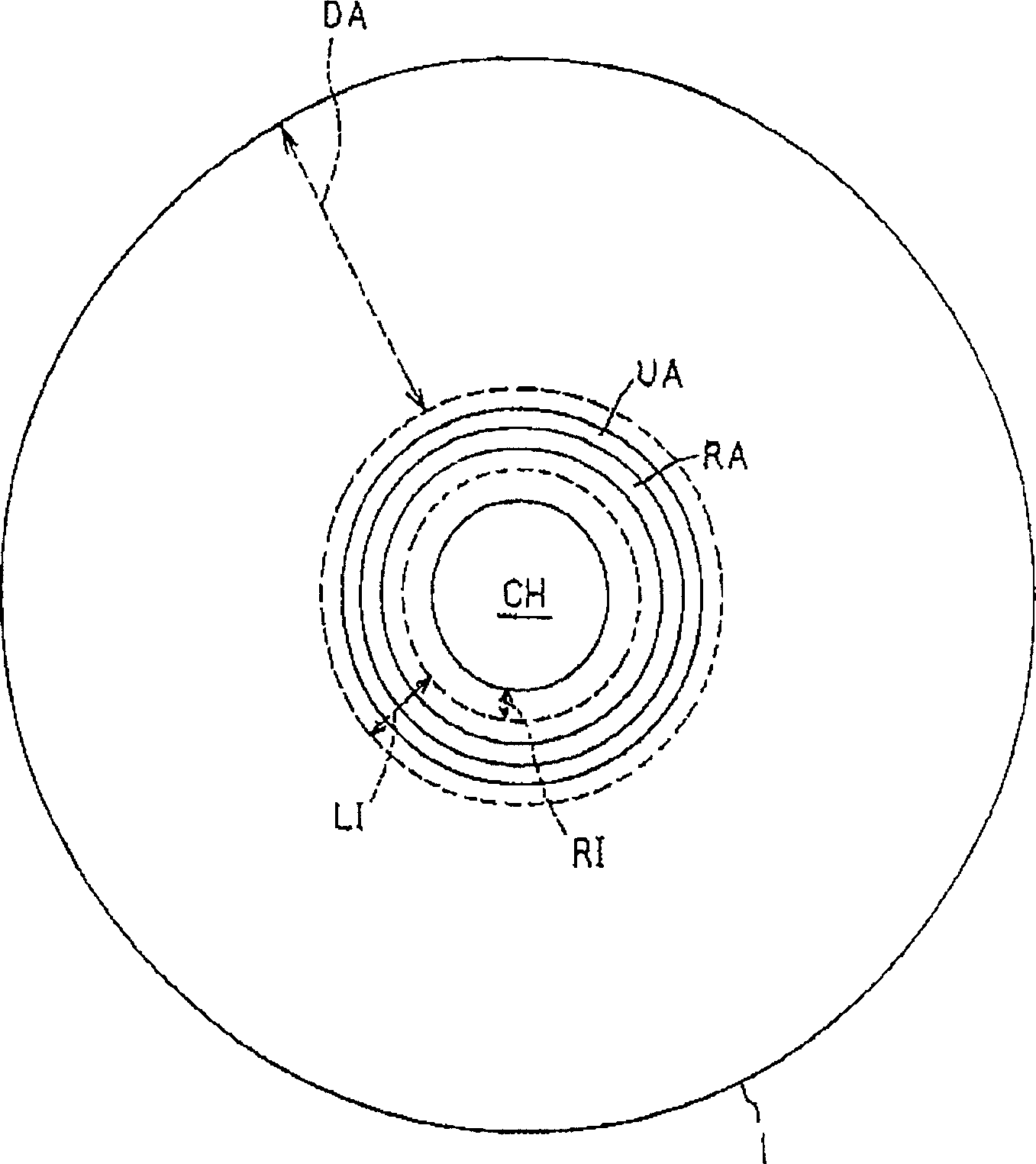
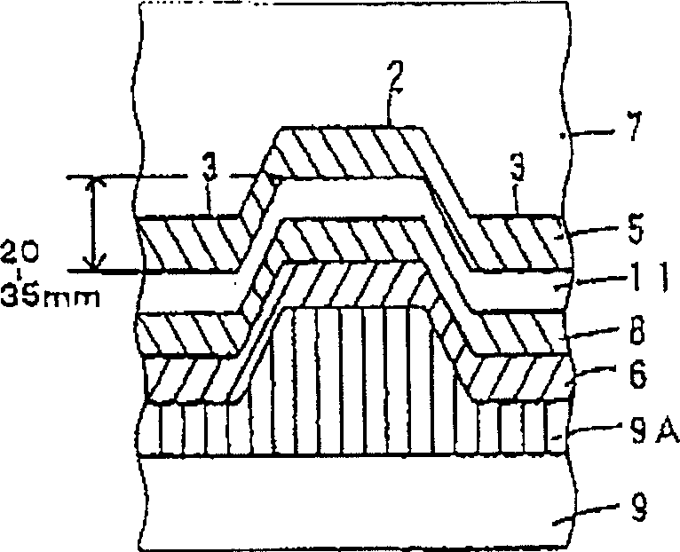
[0109] This embodiment will explain specific examples regarding the reproduction-only area RA and the impossible area UA. In the following example, the fluctuation amplitude and the pit depth of the pit strings with respect to the phase pits PI and PI' are parameters to be appropriately set so that the output levels of the fluctuation signals on the reproduction-only area RA and the impossible area UA are optimized .

[0110] First, the following will refer to Figure 11 and 12 The simulation results are illustrated with respect to the parameters and output characteristics of the fluctuating signal. Figure 11 It is a simulation example of obtaining the relationship between the pit depth (track depth) and the output level of the tracking error signal based on the push-pull method; Figure 12 is a simulation example to obtain the relationship between the fluctuation amplitude and the output level of the fluctuation signal.

[0111] Figure 11 A comparison of the characteri...


PUM


Abstract

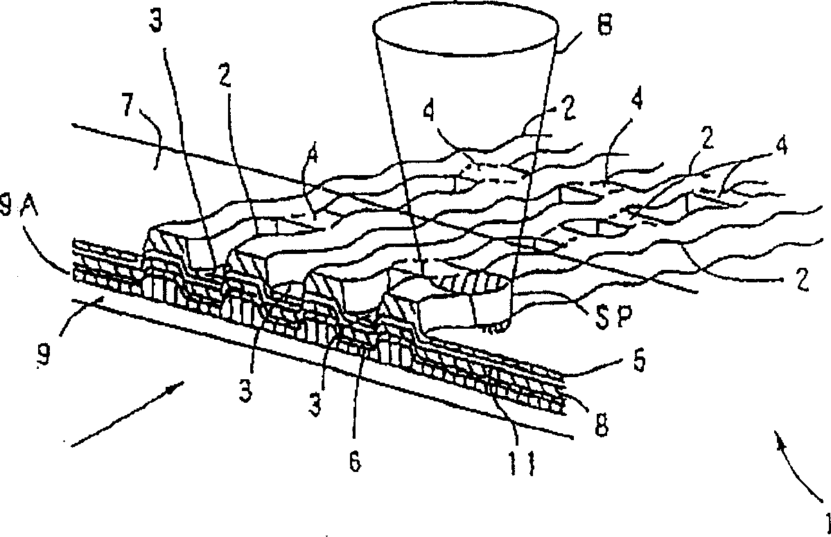
On DVD-RW (1), groove tracks are meanderingly formed on a groove section on which recording information is recorded, and pit strings where a plurality of phase pits (PI, P1') meanderingly are arranged on the impossible area (UA) and the reproduction exclusive area (RA) which prevent illegal copying. On the respective areas, pit depths (groove depths), duty of the pit strings and wobbling amplitudes are set according to predetermined conditions so that the output levels of the wobble signals extracted based on the wobbling amplitudes can be maintained constant on the respective areas. As a result, synchronous control can be made accurately at the time of recording and reproduction on / from the DVD-RW (1). <IMAGE>

Description

[0001] This application is a divisional application of an invention patent application with an application date of July 25, 2001, an application number of 01123073.8, and an invention title of "optical recording medium, optical recording medium production equipment and production method". technical field [0002] BACKGROUND OF THE INVENTION Field of the Invention The present invention relates to an optical recording medium such as a DVD (Digital Video Disc), and more particularly, to an optical recording medium in which recording tracks are formed in a zigzag manner. Background technique [0003] In recent years, DVDs have been widely used as large-capacity optical information recording media. In addition to read-only DVDs (DVD-ROMs), standards are being developed for DVD-RWs (DVD-Recordables) capable of recording and reproducing recorded information. A groove as a recording track is formed in a predetermined pattern on an optical disc in accordance with the DVD-RW standard....

Claims


Application Information

Patent Timeline
Patent Type & Authority Applications(China)
IPC IPC(8): G11B7/005G11B7/007G11B7/013G11B7/24035G11B7/24079G11B7/24082G11B7/24085G11B7/24091G11B7/26G11B20/00
CPCG11B7/007G11B7/24085G11B7/261G11B20/00086G11B20/00586G11B20/00594G11B20/00601
Inventor 山口淳加藤正浩村松英治大岛清朗田切孝夫
Owner PIONEER CORP
Learn More