Eureka AIR delivers breakthrough ideas for toughest innovation challenges, trusted by R&D personnel around the world.

Liquid crystal display device

A technology of a liquid crystal display device and a liquid crystal display panel, which is applied to static indicators, instruments, etc., and can solve the problems of image quality degradation, difficult user comprehensive image quality improvement, large deviation of sensory sensitivity, etc., and achieve the effect of comprehensive image quality improvement

Inactive Publication Date: 2005-12-21
SHARP KK
View PDF1 Cites 9 Cited by
  • Summary
  • Abstract
  • Description
  • Claims
  • Application Information

AI Technical Summary

Problems solved by technology

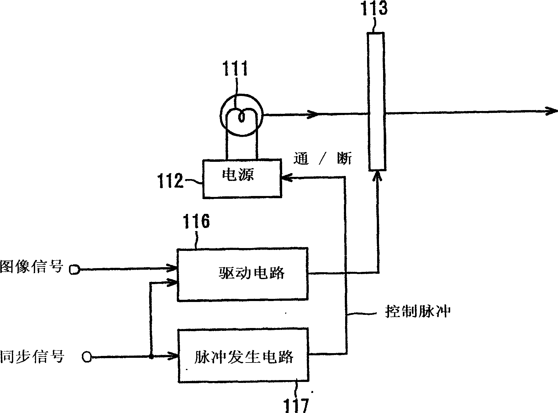
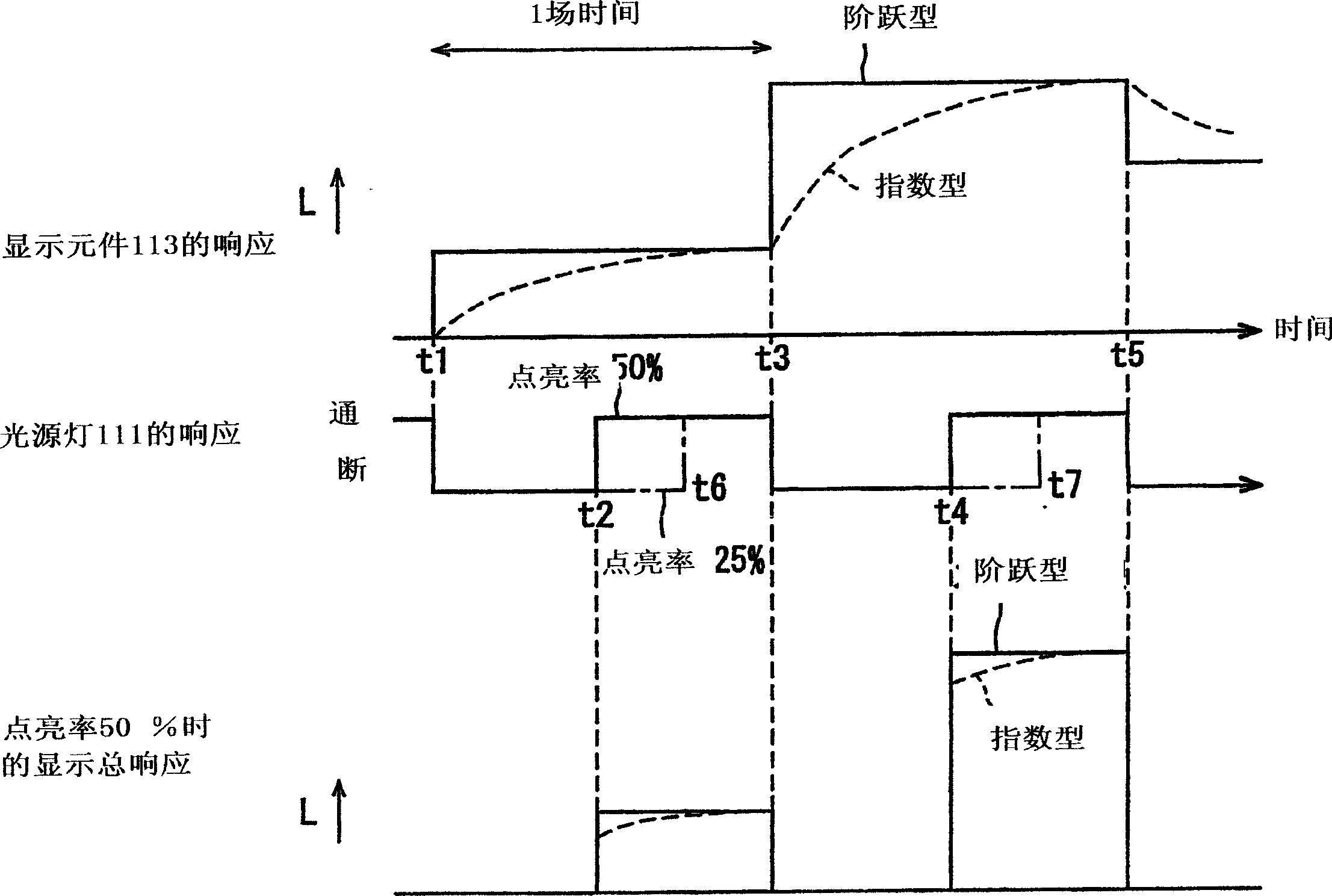
[0023] (2) It can be considered that the visual characteristics when watching moving images have the time integral effect of eyeball movement and vision, and the visual response to the intensity of light stimulation is nonlinear, but the most important tracking movement in eye movement in perceiving moving images (the left and right eyes roughly The characteristics of the same tracking of moving objects) vary depending on the moving speed of the moving object image, and when some image content is displayed with a reduced pulse rate, the above-mentioned stroboscopic defect may occur
[0024] For example, in the case of an image that is moving (full motion) on the full screen in the horizontal direction as in the broadcast of sports such as rugby and volleyball, the image quality degradation due to motion blur is significant, so it is best to reduce the pulse rate as much as possible. In this way, moving image display with reduced motion blur and clear outline can be realized. However, in the case of an image where the person of interest is fixed and the background is moving, reducing the pulse rate will lead to a high possibility of image degradation caused by the above-mentioned stroboscopic defect.
[0025] (3) Moreover, when the pulse rate is reduced, on the opposite side of reducing the motion blur defect of the moving image, the black display time (non-display time of the image) in 1 frame period is increased, so especially in the white image display part Flicker is conspicuous, resulting in deterioration of image quality due to this flicker
[0027] The optimal pulse rate varies depending on the image content, image material, etc., and due to individual differences in users, the sensory sensitivity (dynamic vision) to motion blur, strobe, and flicker varies greatly, so it is difficult to improve the overall image quality for each user. The problem

Method used


Image

  • Liquid crystal display device
  • Liquid crystal display device
  • Liquid crystal display device

Examples


Embodiment approach 1

[0118] 下面,连同图8至 Figure 10 ,详细说明本发明的实施方式1。这里,图8是示出本发明液晶显示装置实施方式1的关键部分概略组成的功能框图。 Figure 9 是用于说明一例本发明液晶显示装置实施方式1的基本工作原理的说明图。 Figure 10 是用于说明另一例本发明液晶显示装置实施方式1的基本工作原理的说明图。

[0119] 如图8所示,本实施方式的液晶显示装置具有分离部1和图像译码部2,前者从用MPEG(活动图像专家组)制式等压缩编码的图像、话音数据和控制数据(内容信息等)的输入复接数据(传输流)分离出各数据,后者对所述分离的图像数据进行MPEG译码。

[0120] 还具有将所述译码的输入图像信号的帧频率变换成高频的帧频率变换部3、变换输入图像信号的灰度级的灰度变换部4、用于根据输入图像信号驱动液晶显示板6的数据电极和扫描电极的电极驱动部5、以及有源矩阵型液晶显示板6。

[0121] 又具有配置在所述液晶显示板6的背面的下射型背后照明光源7、对该背后照明光源7在1垂直显示时间(1帧周期)内进行点亮 / 熄灭的间歇驱动的光源驱动部8、从所述图像译码部2译码后的输入图像信号提取同步信号的同步信号提取部9、从所述分离部1分离的控制数据获取并分析内容信息后根据所述同步信号提取部7提取的同步信号将控制点亮 / 熄灭背后光源7的定时的控制信号输出到光源驱动部8的控制CPU10。

[0122] 这里,控制数据包含的内容数据可用广播台利用CS(CommunicationSatellite:通信卫星)、BS(Broadcasting Satellite:广播卫星)发送来的广播数据中包含的节目信息(体裁信息等)和从DVD(数字多用途光盘)等盘片媒体读出的内容信息。控制CPU10通过分析这些信息检测并判别应显示的图像内容类别后,通过例如参考预先存放各图像内容类别的脉冲率信息的ROM,产生改变背后照明点亮周期(图像显示时间)用的控制信号。

[0123] 这里,内容类别的含义为运动、戏剧、新闻、动画、竞赛等分类。作为上述广播数据包含的内容信息,如果除具有节目体裁、记述类别等的EPG(电子节目指南)信息外,还具有记述快门速度等拍摄条件的拍摄信息、活动模糊附加信息等,控制CPU10可根据该信息检测出应显示图像的内容类别。除上述广播...

Embodiment approach 2

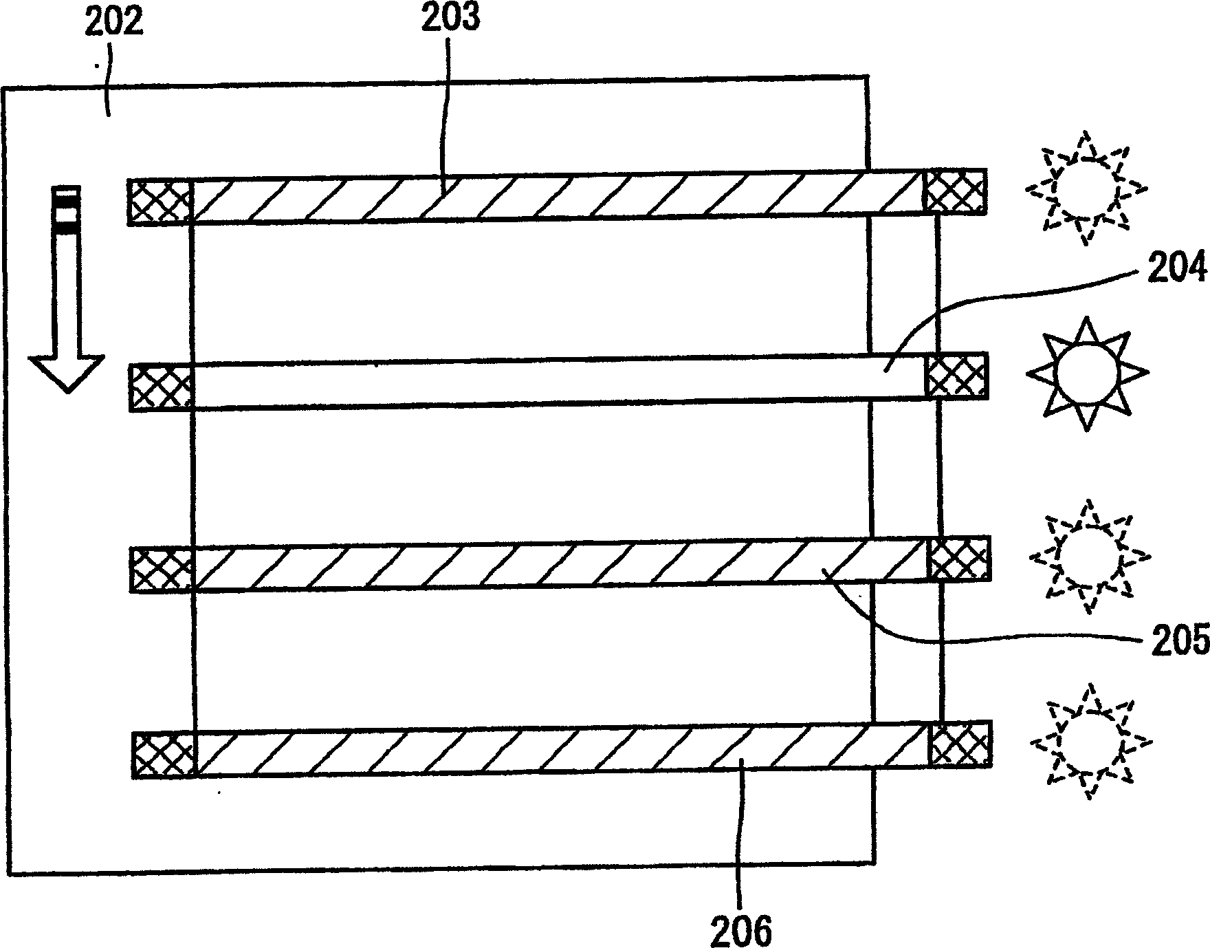
[0154] Next, together with Figure 11 with Figure 12Embodiment 2 of the present invention will be described; the same parts as those in Embodiment 1 above will be denoted by the same reference numerals, and description thereof will be omitted. here, Figure 11 It is an explanatory diagram for explaining an example of the basic operation principle of the liquid crystal display device of this embodiment, Figure 12 It is an explanatory diagram for explaining another example of the basic operating principle of the liquid crystal display device of this embodiment.

[0155] The liquid crystal display device of this embodiment utilizes a scanning type backlight lighting method to prevent motion blurring during moving image display, and its basic functional block diagram is the same as above. figure 1 This block diagram of Embodiment 1 described above is the same. The difference is that a predetermined number (number) of the backlight light sources 7 composed of a plurality of d...

Embodiment approach 3

[0185] Next, together with Figure 13 to Figure 15 说明本发明实施方式3;与上述实施方式2相同的部分标注相同的符号,省略其说明。 here, Figure 13 是示出本实施方式的液晶显示装置关键部分概略组成的功能框图, Figure 14 是用于说明本实施方式的液晶显示装置的电极驱动运作的时序图, Figure 15 是用于说明一例本实施方式的液晶显示装置的基本工作原理的说明图。

[0186] Such as Figure 14 所示,本实施方式的液晶显示装置使背后照明光源7总为点亮状态(连续点亮),并利用1帧周期内对液晶显示板16的图像显示信号写入扫描后接着进行黑显示信号写入扫描(复原扫描)的黑写入型,防止活动显示时产生的活动模糊,其特征为:控制CPU10根据图像内容的类别控制成电极驱动部5的黑显示信号写入定时可变。

[0187] 即,电极驱动部5在1帧周期进行一系列操作:除选择各扫描线用于图像显示外,还再次选择扫描线用于黑显示,同时又根据该选择对数据线供给输入图像信号和黑显示信号。这样,使某帧图像显示和下一帧图像显示之间产生显示黑信号的时间(黑显示时间)。这里,使对图像信号写入定时的黑显示信号显示定时(延迟时间)可随控制CPU10判别的图像内容类别变化。

[0188] 又,控制CPU10连同控制成黑显示时间可变,还控制光源驱动部8,使背后照明光源7的发光亮度可变,或者控制灰度变换部4,使输入图像信号的灰度级可变。这里,提高背后照明光源7的发光亮度(背后照明亮度),同时还在灰度变换部4变换输入图像信号灰度级,以便即使缩短背后照明光源7的点亮时间,输入图像信号与显示亮度的关系也固定。

[0189] 灰度变换部4变换输入图像信号灰度级,以便即使脉冲率变化,也进行伽马特性一致的图像显示。 That is, a conversion table (LUT) for converting the gradation of the input image signal to a gamma (gamma) match is stored in advance in the ROM or the like for each pulse rate, and the grad...


PUM


Abstract

The present invention discloses a liquid crystal display device, which writes the image signal of the frame to be displayed into the liquid crystal display panel (6), and at the same time lights up the backlight source (7) intermittently within one frame period, so as to prevent the display of moving images Activity is blurry. The device includes units (8), (9) that control the lighting time of the backlight light source (7) to be variable according to the detection result of the content category of the image to be displayed. In this way, image quality degradation caused by factors such as motion blur, stroboscopic, and flickering can be properly suppressed.

Description

technical field [0001] The present invention relates to a liquid crystal display device for illuminating a liquid crystal display panel with a backlight source and displaying images, and more particularly to a liquid crystal display device for preventing motion blur during display of moving images by approaching pulse-type display. Background technique [0002] In recent years, efforts have been made to develop flat-panel display devices (FPD) such as liquid crystal display devices (LCD) that can realize high definition, low power consumption, and space saving. Among them, LCDs are used in computer display devices and television display devices. The popularity is very remarkable. However, in contrast to cathode ray tubes (CRTs), which are primarily used for this purpose, the disadvantage of "motion blur" in LCDs can be pointed out, that is, when a moving image is displayed, the viewer perceives the outline of moving parts to be blurred. [0003] For example, as disclosed in...

Claims


Application Information

Patent Timeline
Patent Type & Authority Applications(China)
IPC IPC(8): G09G3/30
Inventor 杉野道幸吉井隆司藤根俊之
Owner SHARP KK
Why Eureka
Eureka Blog
Learn More