Coated cable

A cable and coating technology, applied in the field of cables, can solve the problems of insufficient flexibility, soft noise and soft pulley wear and pulley labor and time, and achieve the effect of prolonging life, preventing wear and preventing wear and damage.

Active Publication Date: 2010-09-01
TOKYO ROPE MFG +1
View PDF6 Cites 4 Cited by
  • Summary
  • Abstract
  • Description
  • Claims
  • Application Information

AI Technical Summary

Problems solved by technology

However, the former still cannot avoid wear and tear due to the direct contact between the side strands.
In addition, in the former and the latter, since the circumscribed circle of the side stranded strands and the pulley often slide relative to each other in metal contact, it still cannot solve the problems of noise generation, wear of the soft pulley, and a lot of labor and time spent on replacing the pulley.
In addition, it is difficult to avoid abrasion due to contact between the core rope and the individual filaments of the side strands, and the rope as a whole tends to have insufficient flexibility against bending.

Method used


Image

  • Coated cable
  • Coated cable
  • Coated cable

Examples


no. 1 approach

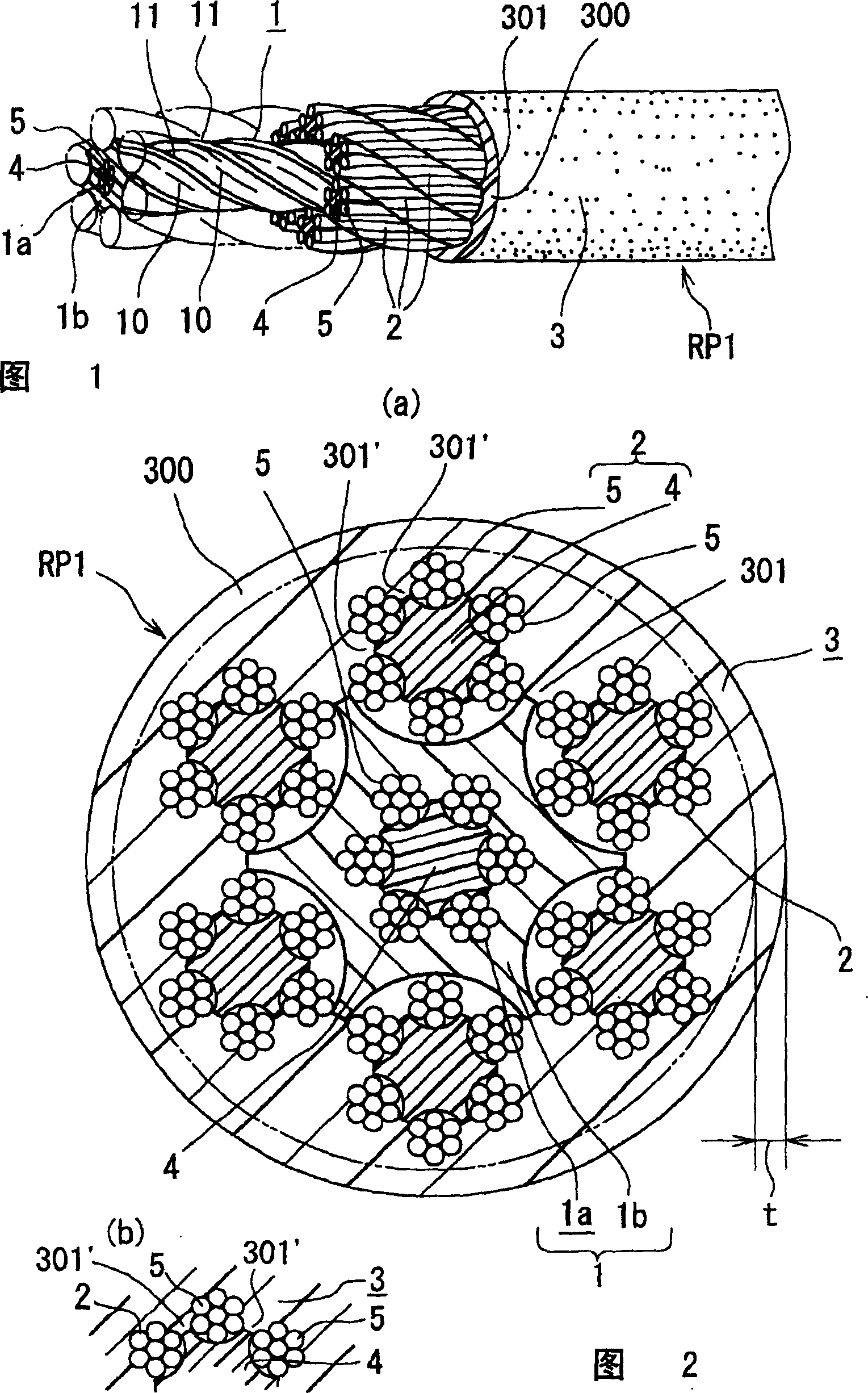
[0048] Figure 1 to Figure 9 A first embodiment of the covered cable of the present invention is shown.

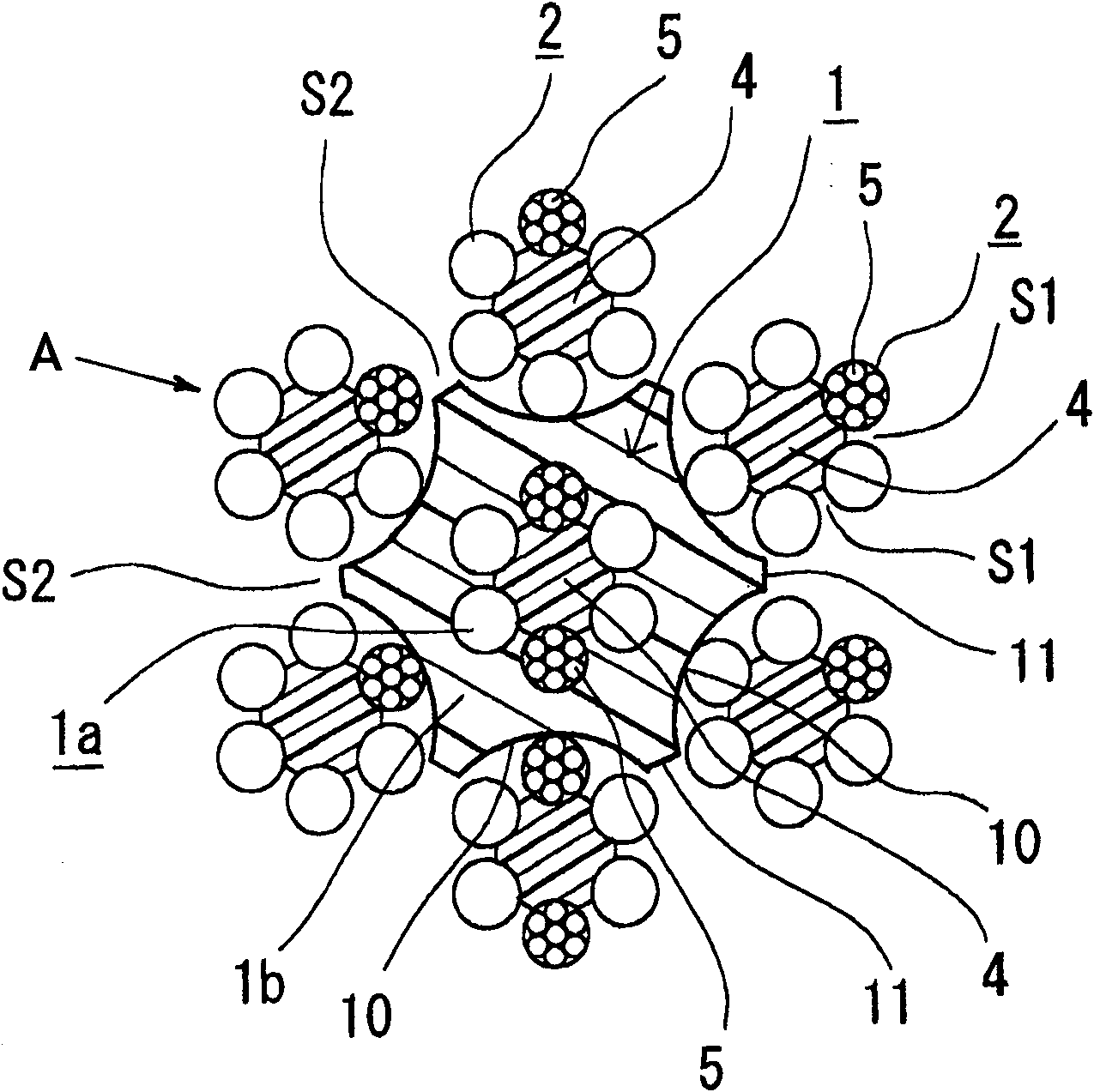
[0049] exist figure 1 In , reference numeral RP1 denotes the entire rope, which is composed of a single core rope 1 , a plurality of side members 2 , and an integral covering resin 3 applied so as to cover the side members 2 . In this example, the rope structure is 7×(6×7).

[0050] Corso 1 in Figure 4 2 shows the state of a single body, and the resin coating layer 1b is provided on the inner core cord main body 1a. The above-mentioned core cord main body 1a is constituted by a combined rope structure in which six twisted strands 5 are arranged and twisted around a rod-shaped or linear synthetic resin core 4 . In this embodiment, the side member 2 is constituted by a composite rope structure in which six twisted strands 5 are arranged and twisted around a synthetic resin core 4 .

[0051] The above-mentioned synthetic resin core 4 functions to improve the ductility ...

no. 2 approach

[0097] Figure 11 and Figure 12 A second embodiment of the cable of the invention is shown. In the rope of this embodiment, reference numeral RP3 denotes the whole, and is composed of a single core cord 1 , a plurality of side members 2 , and an integral covering resin 3 applied so as to cover the side members 2 . The rope structure is IWRC+8×S(18).

[0098]Since the core cable 1 of the second embodiment is the same as that already described, only the difference will be described, and a plurality of side members 2 (eight in the figure) are used. Each side member 2 is composed of a multi-layered twisted strand. The structure is arbitrary, but in this example, it is composed of 8×S(18), in other words, 8×S(a+9+9).

[0099] That is, nine relatively thin monofilaments 203 are arranged and twisted around the thick synthetic resin core 4 to form the inner layer 2a, and nine side monofilaments 202 with relatively thick diameters are arranged and twisted around the inner layer 2a...


PUM

PropertyMeasurementUnit
Melting pointaaaaaaaaaa
Tensile strengthaaaaaaaaaa

Abstract

The invention provides a covered wire rope for a running wire, having good flexibility against bending, prevented from abrasion caused by the contact of wires of a core rope and side members with each other, the contact of the core rope with the side members and the contact of the side members with each other, and achieving good transmission of driving force to a sheave and silence. The core ropehas a core rope body having a synthetic resin core and two or more side strands arranged around the resin core and twisted so as to have spaces between them at one or more parts, and a resin coveringlayer including the core rope body. The side member has a synthetic resin core and two or more strands or wires twisted around the core. The resin covering layer has spacer parts at the outer periphery, and uniform spaces are formed among respective side members by the spacer parts. A resin layer integrated with the resin layer of the outer layer, going over the circumcircle of the side member fills the spaces, and also fills the spaces among the strands or wires of each of the side members.

Description

technical field [0001] The present invention relates to a cable, and more particularly to a sheathed cable suitable for use as a moving cable in a crane or an elevator. Background technique [0002] Moving ropes, such as hoisting ropes for elevators or ropes for loading and unloading machinery such as cranes, move through pulleys and are wound up on drums, so they are under strict conditions that tension and bending act on the entire length. under. In addition, for example, for hoisting ropes of elevators, it is strongly desired to reduce the diameter of pulleys and downsize the system, and in order to achieve this, it is essential to improve the bending fatigue resistance of the cables used. [0003] Conventionally, as a rope for a moving rope used under the condition that the ratio D / d of the pulley diameter D to the rope diameter d is about 40, as stipulated in Japanese Industrial Standards G 3525 or 3546, etc., the following is used. The rope of the above structure: it...

Claims


Application Information

Patent Timeline
IPC IPC(8): D07B1/16
CPCD07B2201/2061D07B1/162D07B2501/2007D07B2201/2049D07B2205/2064D07B2501/2015D07B2207/404D07B7/145D07B1/165D07B1/068D07B2201/2065D07B2207/4059D07B2201/1014D07B2801/24D07B2801/22D07B2801/60D07B1/16
Inventor 守谷敏之古川一平高桥龙彦早野富夫岩仓昭太佐佐木康二前田太一
Owner TOKYO ROPE MFG
Why Eureka
Try Eureka